
Operations and Maintenance Manual


_
MPR 4.1
Reader Maintenance Instructions
Confidential UM UM360479-100 Revision: Draft B4 Page 88 of 246
© Kapsch TrafficCom Canada Inc. 2022
All information contained herein is proprietary to, and may only be used with express, written permission from, Kapsch TrafficCom Canada Inc.
FILE: UM360479-100 REV B4 DRAFT WIP MPR-4.1 READER OPERATIONS AND MAINTENANCE MANUAL (002).DOCX
05/25/2022 11:18
Kapsch TrafficCom
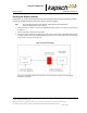
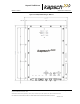
Figure 5-5: Pole Mounting an MPR 4.1
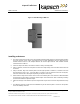
Installing an Antenna
1. The antenna mounts on a frame using 2-inch diameter galvanized pipe clamps. For 12 ft wide lanes position
the center antenna at lane center of the defined lane. For ORT applications with 12 ft wide lanes, the
straddle antenna must be at the midpoint between the left and right antennas. Note straddle min/max
measurements in Table 5-2.
2. Orient the weep holes down, such that the radome is facing oncoming traffic.
3. Using a tilt meter, measure the road pitch and cross lane slope directly under each IAG antenna. Record
the results.
4. Using a tilt meter, align each antenna plate to the tilt angle specified in Table 5-2, in relation to the road
pitch measured in step 3 (e.g., If the road pitch is 2 degrees. and the antenna tilt must be 10 degrees,
mount the antenna at 8 or 12 degrees depending on the pitch of the road.)
5. Ensure that the height of the antenna at the center of the radiating face of the antenna as tilted falls within
the height range given Table 5-2. Please contact Kapsch Technical Service when considering mounting
the antennas outside the specified heights.
6. Adjust the roll angle of the antenna equal to 0 degrees with respect to the cross lane slope obtained in step
3.
7. For TDM-only protocol, an ORT antenna installation may be all antennas (IAG 1 or IAG 2 or IAG 3) inline
across the roadway as shown