
Operations and Maintenance Manual

_
MPR 4.1
Reader Maintenance Instructions
Confidential UM UM360479-100 Revision: Draft B4 Page 73 of 246
© Kapsch TrafficCom Canada Inc. 2022
All information contained herein is proprietary to, and may only be used with express, written permission from, Kapsch TrafficCom Canada Inc.
FILE: UM360479-100 REV B4 DRAFT WIP MPR-4.1 READER OPERATIONS AND MAINTENANCE MANUAL (002).DOCX
05/25/2022 11:18
Kapsch TrafficCom
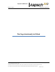
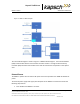
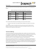
Figure 4-1: MPR 4.1 Block Diagram
The internal block Diagram is shown in Figure 4-1: MPR 4.1 Block Diagram. The controller Module
(CTM) communicates with the Lane Controller and other readers. Through the Channel Group
Controller (CGC) the CTM communicates to the radio to interact with Transponders in the capture
zone.
External Power
The MPR 4.1 operates from an external DC power source that provides 19 to 30VDC at 50 Watts of
power.
The external power supply shall supply clean DC power at the MPR 4.1 connector that meets the
following requirements:
• 19 to 30 VDC at the MPR 4.1 connector