
Operations and Maintenance Manual

_
MPR 4.1
Reader Maintenance Instructions
Confidential UM UM360479-100 Revision: Draft B4 Page 99 of 246
© Kapsch TrafficCom Canada Inc. 2022
All information contained herein is proprietary to, and may only be used with express, written permission from, Kapsch TrafficCom Canada Inc.
FILE: UM360479-100 REV B4 DRAFT WIP MPR-4.1 READER OPERATIONS AND MAINTENANCE MANUAL (002).DOCX
05/25/2022 11:18
Kapsch TrafficCom
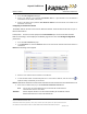
4. Go to the Lane Assignment web page.
5. Assign an IP address to the parameter Inter-Reader alias on a given Reader so that the Reader is
accessible on the IR network, if necessary.
6. Assign an IP address to the parameter Inter Reader IP Address so that the Reader is accessible on the
IR network, if necessary.
Configuring an LC Ethernet network
The Reader data can be sent to the LC via an Ethernet network. Note the data can be sent to up to 3
Ethernet destinations
Prerequisites: Connect a service laptop to the Lane Controller port to access the web interface.
Refer to Connecting a service laptop to the Reader, page 34. You must have Change Configuration
permissions.
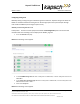
1. Go to the Lane controller web page.
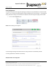
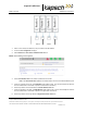
2. In the Destination row, select the Ethernet check box for each RF Port that will communicate with the LC
via Ethernet.
Result: The following screen appears.
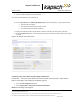
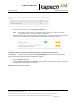
3. Enter the LC IP address and Port number for each RF Port.
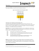
4. If all the RF Ports will be communicating with the LC at the same IP address, click the clone icon to
duplicate settings automatically to all channels.
Result: All RF Ports selected to communicate over Ethernet will now have the same destination LC IP.
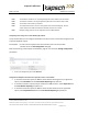
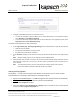
5. Enter a time, in milliseconds (ms), in the LC Ethernet TCP-Socket Timeout field.
Note: If an LC does not respond within this time, the Reader will consider Ethernet
communications to the LC to be down.
Attention: Contact Kapsch Service to set the Land Controller port IP address if the IP
address has been lost or cannot be determined.