
Operations and Maintenance Manual

_
JANUS
®
Multi-Protocol Reader 2.4 Operating Instructions
Confidential UM 360467-110 Revision: B Page 31 of 247
© Kapsch TrafficCom Canada Inc. 2021
All information contained herein is proprietary to, and may only be used with express, written permission from, Kapsch TrafficCom Canada Inc.
FILE: UM 360467-110 REV B3 MPR 2.4 CLEAN.DOCX 03/02/2021 1:01
Kapsch TrafficCom
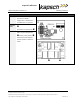
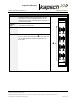
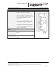
Control Module (CTM)
Function
Contains the Reader processor (MC),
the Channel Group Controller module
(CGC). Combined these control the
operation of the RF modules.
CTM ON/OFF switch
Units per
Redundant
Reader
One CTM on primary side,
One CTM on secondary side
Normal State
The POWER LED illuminates green
when the CTM is on and is receiving
power from the PSM.
The STATUS LEDs illuminate green
to indicate SYNC is functional, CTM is
active, CGC is functional and MC is
functional.
See Table 6-1 for more information on
CTM LED indicators.
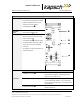
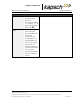
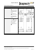
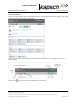
Connections
Port
Function
ETHERNET 1 - 1 Gbps
Multiple functions, including connecting to external
Ethernet lane controllers; connecting a service
laptop for intial reader set-up.
ETHERNET 2 – 1 Gbps
For connecting several Readers together to create
an Inter-Reader (IR) network, or for connecting a
service laptop when Ethernet 1 is connected to the
Lane Controller.
DIAGNOSTIC PORT
Serial port access to the reader, intended for
Kapsch sercvice use.