
Operations and Maintenance Manual


_
JANUS
®
Multi-Protocol Reader 2.4 Operating Instructions
Confidential UM 360467-110 Revision: B Page 24 of 247
© Kapsch TrafficCom Canada Inc. 2021
All information contained herein is proprietary to, and may only be used with express, written permission from, Kapsch TrafficCom Canada Inc.
FILE: UM 360467-110 REV B3 MPR 2.4 CLEAN.DOCX 03/02/2021 1:01
Kapsch TrafficCom
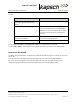
• One Circulator adapter cable LMR -400. (3’5” for 902-904MHz, 3’3” for all other frequencies) (not
required for MRFM-S Plus)
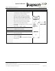
The redundant Reader consists of:
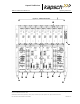
Note: Numbers in the list below refer to those associated with Figure 2-1: A Redundant Reader. The DSM,
and CFM are not shown in the figure.
• One rack and Distribution Module
• Two Controller Modules (CTM), each equipped with an internal Main Controller (MC) and one
Channel Group Controller (CGC)
• Two Configuration Modules (CFMs) attached directly to the DSM
• One Synchronization Port Module (SPM)
• Two Lane Port Modules (LPM)
• One secondary Power Supply Module (PSM)
• One primary Power Supply Module (PSM)
• AC Power cords for the PSM’s
Note: Non-redundant Readers contain one CTM, one CFM, one LPM, and one PSM. For an illustration of a
non-redundant reader, see Appendix C.
Additional installation components required are:
• Two RF cables from Reader to Circulator (type N male to type N female) (MRFM-S Only)
• Sealing tapes for RF connectors exposed to weather
• Lightning arrestors
• Optional Ethernet switch modules (ESMs)
• Sync and inter-reader Ethernet cabling (if required)
• Ethernet cables if ESMs used
• 300 CFM fan tray for operation above 131F (55C)
Additional Site requirements are:
• Cabinet with AC power, grounding, including reader ground bar,
• Mounting structure for antenna
• Ethernet or Serial cables to connect to the lane Controller(s)