
Operations and Maintenance Manual


_
JANUS
®
Multi-Protocol Reader 2.4 Operating Instructions
Confidential UM 360467-110 Revision: B Page 23 of 247
© Kapsch TrafficCom Canada Inc. 2021
All information contained herein is proprietary to, and may only be used with express, written permission from, Kapsch TrafficCom Canada Inc.
FILE: UM 360467-110 REV B3 MPR 2.4 CLEAN.DOCX 03/02/2021 1:01
Kapsch TrafficCom
2. OVERVIEW
Introduction
The JANUS
®
Multi-Protocol Reader 2.4 (MPR 2.4) is part of the Electronic Toll Collection (ETC) Subsystem. Toll
collection is the primary use of the Reader.
Overview of the MPR 2.4 Electronic Toll Collection (ETC) Subsystem
The MPR 2.4 Reader can interact with both active and passive OBUs. The MPR 2.4 is factory configured to
enable all protocols. For an in-depth description of protocols and the MPR 2.4 ETC Subsystem, see Theory of
Operations page 139.
Active OBU
For an active OBU, overhead antennas send out RF signals. As a vehicle equipped with an active OBU
approaches a toll zone, the OBU receives an RF signal from the antenna. The OBU then starts transmitting data,
which is received by the antenna and passed on to the Reader via an MRFM-S module. The Reader processes
and logs the OBU data, and then sends the information to the Lane Controllers (LCs). The Reader can also send
data back to the OBU, such as an updated toll account balance.
Passive OBU
For a passive OBU, the antenna sends out a command or a continuous wave via an RF signal. As a vehicle
equipped with a passive OBU approaches a toll zone, the OBU receives an RF signal from the antenna. If
commanded, the OBU then starts transmitting data, which is received by the antenna and passed on to the
Reader via an MRFM-S or MRFM-S Plus module. The Reader processes and logs the OBU data, and then sends
the information to the Lane Controllers (LCs). The Reader can also send data back to the OBU, such as an
updated toll account balance.
Th
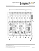
JANUS MPR 2.4 system components
Figure 2-1: A Redundant Reader shows a rack equipped with eight Smart Multi-protocol Radio Frequency
modules (MRFM-S).
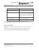
A Lane Kit consists of:
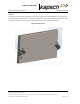
• An antenna (see Figure 2-2)
• An MRFM-S( in Figure 2-1: A Redundant Reader) or an MRFM-S Plus
o NOTE: MRFM-S and MRFM-S Plus cannot be combined in one reader.
• Two feedline adapter cables (2 for MRFM-S and 1 for MRFM-S Plus)
• One Circulator (not required for MRFM-S Plus)