
Operations and Maintenance Manual


_
JANUS
®
Multi-Protocol Reader 2.4 Maintenance Instructions
Confidential UM 360467-110 Revision: B Page 196 of 247
© Kapsch TrafficCom Canada Inc. 2021
All information contained herein is proprietary to, and may only be used with express, written permission from, Kapsch TrafficCom Canada Inc.
FILE: UM 360467-110 REV B3 MPR 2.4 CLEAN.DOCX 03/02/2021 1:01
Kapsch TrafficCom
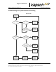
Reader recovery actions
For certain failures, the Reader will automatically initiate the recovery actions outlined in Table 6-5.
Table 6-5: Failures and the Reader Recovery Actions they trigger
Failure
Reader Recovery Action
CGC Health failure
reinitializes CGC on failed side
Serial LC link down
re-attempts connection on failed side once every
second
Ethernet LC link down
re-attempts connection on failed side once every
second or up to 10 seconds based on load
Inter-Reader Ethernet link down
switches to Badger style CRA on failed side to re-
attempt connection
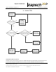
Testing the CTM Ethernet 1 port
This test verifies that a CTM Ethernet 1 port is working properly.
Prerequisites: A service laptop.
1. Connect a service laptop directly to CTM Ethernet 1 port being tested. Refer to Connecting a service laptop
to the Reader, page 42.
2. Check “ping” operation. If ping responds correctly, this confirms the Ethernet 1 port is functional.
Testing the Synchronization Circuit
This first part of this test checks the functionality of one Reader’s SPM. The second part of this test checks the
Synchronization wiring from one Reader’s SPM to the synchronization circuit terminal block
Prerequisites: At least one RF module installed in the Reader. Both Primary and Secondary CTMs have the same
configuration; synchronization enabled
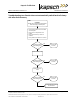
Testing the SPM and CTM
1. Disconnect the Synchronization circuit wiring from the SPM terminal block
Using two short jumper wires connect Tx+ to Rx+ and Tx- to Rx- on the SPM terminal block, leaving the GND
terminals unconnected (see SPM terminal block connections, page 224).
If the SYNC LED on both CTM’s illuminates solid green, the SPM and CTM’s are functioning properly.
Reconnect the synchronization circuit to the SPM terminal block.
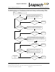
Testing the Synchronization hub cabling
1. If the SYNC LED on the CTM does not illuminate solid green with a functional SPM and CTM connected to
the Synchronization circuit, the problem is with the wiring between the SPM and the synchronization hub
terminal block.