
Operations and Maintenance Manual

_
JANUS
®
Multi-Protocol Reader 2.4 Maintenance Instructions
Confidential UM 360467-110 Revision: B Page 175 of 247
© Kapsch TrafficCom Canada Inc. 2021
All information contained herein is proprietary to, and may only be used with express, written permission from, Kapsch TrafficCom Canada Inc.
FILE: UM 360467-110 REV B3 MPR 2.4 CLEAN.DOCX 03/02/2021 1:01
Kapsch TrafficCom
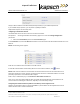
Configure how multiple transactions are reported to the LC in IR network:
• To send one transaction report per OBU to the LC without informing the LC of suppressed reports,
select Disabled from the Cross-Reader Reporting box.
• To send all transaction reports (one per reader) for an OBU to the LC, select Report All from the
Cross-Reader Reporting box.
• To send one transaction report per OBU to the LC and also inform the LC of suppressed reports,
select Report Non-zero from the Cross-Reader Reporting box.
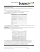
Configuring Left and Right Adjacent Readers
For proper Inter-Reader lane assignment across adjacent readers, a reader must be configured with a “Left”
neighbor, a “Right neibhbor, or both, according to the following definitions.
Left Reader (“low channel neighbor”)
Enable the “Left Reader” setting if a reader’s lowest in use channel is adjacent to another reader’s channels.
This is regardless of direction of travel. A channel is considered “in-use” if it is configures as Active or Guard on
the Channels configuration page.
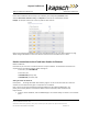
Right Reader (“high channel neighbor”)
Enable the “Right Reader” setting if a reader’s highest in-use channel is adjacent to another reader’s channels.
This is regardless of directionof travel.
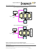
Note: Regardless of the channel firing sequencethe physical antenna placement must align with the RF
channel order. This means adjacent channels connecto adjacent antennas. This is regarless of the
direction of travel. This is the case in the example below.
Note: At the reader seem between and two adjacent reader, on lane must be matched to a high channel
number (e.g. Channel 5) whereas the adjacent lane from the adjacent reader must be matched to the
lowest channel number (e.g. channel 1). This is the case in the example below.
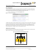
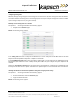
The following example shows how to configure the IR settings based on where the Reader sits in the site.
Example: Reader 1 in Figure 5-15 has a Reader on its right (Reader 2) but no Reader on the left. Reader 2 in
Figure 5-15 has a Reader on its right (Reader 3) and a Reader on its left (Reader 1). Reader 3 in Figure 5-15 does
not have a Reader on its right but has one on its left (Reader 2).