
Operations and Maintenance Manual

_
JANUS
®
Multi-Protocol Reader 2.4 Maintenance Instructions
Confidential UM 360467-110 Revision: B Page 172 of 247
© Kapsch TrafficCom Canada Inc. 2021
All information contained herein is proprietary to, and may only be used with express, written permission from, Kapsch TrafficCom Canada Inc.
FILE: UM 360467-110 REV B3 MPR 2.4 CLEAN.DOCX 03/02/2021 1:01
Kapsch TrafficCom
Assign a static IP address and Subnet Mask (netmask) according to your network requirements.
If your network design requires it, you can provide a gateway IP address.
Repeat above steps for the secondary CTM.
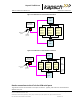
Configuring an LC Ethernet network
The Reader data can also be sent to the LC via an Ethernet network.
Prerequisites: Accessing the Reader web interface, page 42. You must have Change Configuration
permissions.
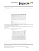
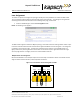
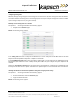
1. Select the LC Destination panel on the Lane Controller page.
In the Destination row, select the Ethernet check box for each RF channel that will communicate with the LC via
Ethernet.
Result: The following screen appears.
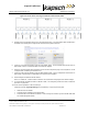
Enter the LC IP address and Port number for each RF channel.
If all the RF channels will be communicating with the LC at the same IP address, click button.
Result: All RF channels selected to communicate over Ethernet will now have the same destination LC IP.
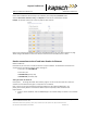
Note: When setting the LC Retry Timeout, consider the baud rate used to communicate with the LC and the
processing speed of the LC to avoid false failure reports.
Enter a time, in milliseconds (ms), in the LC Ethernet TCP-Socket Timeout field.
Note: If an LC does not respond within this time, the Reader will consider Ethernet communications to the
LC to be down and could trigger a switchover, depending on the redundancy settings.
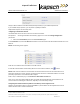
Configuring the Reader IP Address (Ethernet 1 IP address) via the Diagnostic Port
Attention: Contact Kapsch Service to set the ETHERNET 1 port IP address via the Diagnostic Port if the IP
address has been lost or cannot be determined.