
Operations and Maintenance Manual

_
JANUS
®
Multi-Protocol Reader 2.4 Maintenance Instructions
Confidential UM 360467-110 Revision: B Page 163 of 247
© Kapsch TrafficCom Canada Inc. 2021
All information contained herein is proprietary to, and may only be used with express, written permission from, Kapsch TrafficCom Canada Inc.
FILE: UM 360467-110 REV B3 MPR 2.4 CLEAN.DOCX 03/02/2021 1:01
Kapsch TrafficCom
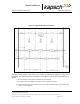
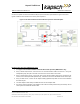
Use of this amplifier should be reviewed with Kapsch personnel before implementation. Figure 5-9 shows a
typical installation that includes the use of the power amplifiers.
Figure 5-9: RF Cable Installation Schematic Bi-Static Operation with RF Amplifier
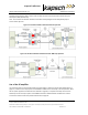
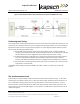
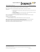
For Mono-Static Operation (MRFM-S Plus only)
1. See Figure 5-10: RF Cable Installation Schematic Mono-Static Operation (MRFM-S Plus only)
2. Using a 10in-lb torque wrench, connect the one end of the RF feedline cable to the antenna. Using self-
amalgamating tape, wrap the connection at the antenna to ensure water cannot enter.
3. Using a 10in-lb torque wrench, connect the other end of the RF Feedline cable that is connected to the
antenna, to the RF Adaptor Cable (800125-001), that will be connected to the MRFM-S Plus antenna port.
4. Using an SMA wrench, connect the RF Adapter Cable(s) (800125-001) SMA connector to the MRFM-S
Plus antenna port.
5. Tie all RF Adapter cables neatly and label both ends of each adapter cable.
6. Secure the service loop portion of the feedline to the antenna-mounting bracket using the tie wraps. Do not
severely bend or kink the RF feedline cable.