
Operations and Maintenance Manual


_
JANUS
®
Multi-Protocol Reader 2.4 Maintenance Instructions
Confidential UM 360467-110 Revision: B Page 162 of 247
© Kapsch TrafficCom Canada Inc. 2021
All information contained herein is proprietary to, and may only be used with express, written permission from, Kapsch TrafficCom Canada Inc.
FILE: UM 360467-110 REV B3 MPR 2.4 CLEAN.DOCX 03/02/2021 1:01
Kapsch TrafficCom
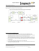
Circulator and the antenna. Ports 1 and 3 of the circulator are then connected to the RF modules using the
RF Adaptor Cables (800125-001).
Note: The circulators are weather resistant, but should be entirely wrapped in self-amalgamating tape to
ensure a water tight seal.
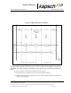
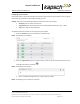
Figure 5-7: RF Cable Installation Schematic Bi-Static Operation
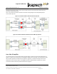
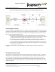
Figure 5-8: RF Cable Installation Schematic Bi-Static TDM Only Operation
Use of the RF amplifier
The maximum cable loss and associated maximum cable length, as defined in the RF Cable Specifications on
page 227, is based on the output power of the MRFM-S module and the sensitivity of the transponders. When
the site specific application exceeds the limits defined on page 227, an amplifier assembly can be used to
effectively increase the output power of the MRFM-S module an additional 6dB. This 6dB is then used to
increase the maximum cable loss permitted as defined on Page 227.