
Operations and Maintenance Manual


_
JANUS
®
Multi-Protocol Reader 2.4 Maintenance Instructions
Confidential UM 360467-110 Revision: B Page 161 of 247
© Kapsch TrafficCom Canada Inc. 2021
All information contained herein is proprietary to, and may only be used with express, written permission from, Kapsch TrafficCom Canada Inc.
FILE: UM 360467-110 REV B3 MPR 2.4 CLEAN.DOCX 03/02/2021 1:01
Kapsch TrafficCom
Installing the RF cables
CAUTION:
Excessive bending or kinking can damage the RF feedline cables. Do not
excessively bend or kink the RF feedline cables while fishing them through
the rigid conduit from the antenna to the Reader enclosure.
1. Place the RF feedline cable(s) in position. Use an appropriate cable type (coaxial or Heliax) to ensure the
RF feedline cable does not produce a signal loss greater than permitted, see Appendix A RF Cable
Specification. Use flexible cable (LMR400 preferred) for the short feedline cable between the circulator and
the antenna
Using tie wraps, create a service loop of 6 ft. at both ends of the RF feedline cable(s). Trim the excess cable length.
Install spiral wraps on the RF feedline cable(s) where necessary to protect it from abrasion.
Using marker tie wraps and label sets, label the Reader end of each RF feedline (ex. TX Lane 1 or RX Lane 1), each
antenna RF feedline (ex. Tx lane 1 or Rx lane 1).
Attach the N-Type male connector to the antenna end of the RF feedline cable(s) . Firmly crimp the male connector.
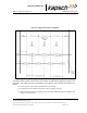
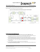
For Bi-Static Operation (MRFM-S only)
1. See Figure 5-7: RF Cable Installation Schematic Bi-Static Operation
2. Using a 10in-lb torque wrench, connect the first RF feedline cable to the Circulator (Port 1). Using self-
amalgamating tape, wrap the connection and the circulator to ensure water cannot enter.
Using a 10in-lb torque wrench, connect the second RF feedline cable to the Circulator (Port 3). Using self-
amalgamating tape, wrap the connection and the circulator to ensure water cannot enter.
Using a 10in-lb torque wrench, connect a third (39 inch long) RF feedline cable to the Circulator (Port 2). Using
self-amalgamating tape, wrap the connection and the circulator to ensure water cannot enter.
Using a 10in-lb torque wrench, connect the other end of the third (39 inch long) RF feedline cable that is connected
to Port 2 of the Circulator, to the antenna. Using self-amalgamating tape, wrap the connection to ensure water
cannot enter.
Attach the N-Type female connector to the reader end of the first RF feedline cable. Firmly crimp the female
connector.
Using a 10in-lb torque wrench, connect the other end of the first RF Feedline cable that is connected to Port 1 of the
Circulator, to the RF Adaptor Cable (800125-001), that will be connected to the “Antenna” Port of the MRFM-S.
Attach the N-Type female connector to the reader end of the second RF feedline cable. Firmly crimp the female
connector.
Using a 10in-lb torque wrench, connect the other end of the second RF Feedline cable that is connected to Port 3
of the Circulator, to the RF Adaptor Cable (800125-001), that will be connected to the “RX” Port of the MRFM-S.
Using an SMA wrench, connect each RF Adapter Cable(s) (800125-001) SMA connector to the assigned MRFM-S
module port(s).
Tie all RF Adapter cables neatly and label both ends of each adapter cable.
Secure the service loop portion of the feedline to the antenna-mounting bracket using the tie wraps. Do not severely
bend or kink the RF feedline cable.
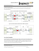
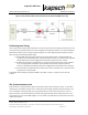
Note: For a TDM and/or 6C protocol configuration (i.e., no other passive protocols), the Circulator can be
located in the cabinet with the reader and one RF feedline cable is connected between port 2 of the