
Operations and Maintenance Manual

_
JANUS
®
Multi-Protocol Reader 2.4 Maintenance Instructions
Confidential UM 360467-110 Revision: B Page 160 of 247
© Kapsch TrafficCom Canada Inc. 2021
All information contained herein is proprietary to, and may only be used with express, written permission from, Kapsch TrafficCom Canada Inc.
FILE: UM 360467-110 REV B3 MPR 2.4 CLEAN.DOCX 03/02/2021 1:01
Kapsch TrafficCom
• If separations are below this there is a higher risk of reports from multiple lanes for the same tag. Note
the use of the voting algorithms will correctly assign the tag to the correct lane). There may also be
some reduction in the read performance for passive protocols.
• If the physical lane width exceeds 15 ft.(4.57 m), the lane should be treated as a multi-lane free flow
configuration and multiple lane kits used per lane. The antenna spacings should be kept at 12 ft
separation in each row.
• The same FDM channel frequency should not be used on adjacent lanes, including straddle and
shoulder lanes (recommended at least 24 ft. separation between in-line antennas and 21 ft for
staggered antennas).
• NOTE: It is preferable to use more frequencies where possible to minimize inter-channel
interference due to FDM.
• Two TDM channels that are configured active in the same time slot should not be used on adjacent
lanes, including straddle and shoulder (recommended at least 24 feet separation between in-line
antennas and 21 ft for staggered antennas).
• NOTE: It is preferable to use the minimum number of TDM slots to minimize the (repeating) time
length of the Frame Sequence and maximize handshake count.
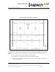
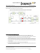
Along track alignment
The capture zone created by an antenna is a function of tuning, tilt angle, antenna used, height and reflective
properties of the site. There is no single value that can be used to define the alignment of the antenna center
to the capture zone. As a guideline nominally 75% of the Capture zone is in front of the antenna center.
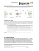
Multiple readers
Where multiple readers are on a site, the following additional guidelines apply:
• The readers must be synchronized and running the same Frame Sequence configuration, or
compatible Frame Sequence configurations.
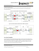
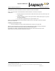
Installing the MRFM-S modules
Note: MRFM-S or MRFM-S Plus modules can be replaced while the Reader is powered on and the DSM
energized.
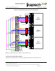
CAUTION:
To avoid damaging the modules, ensure that alignment of both
the connector on the module and the connector on the DSM
(backplane) is correct before securely plugging the module into
the DSM.
1. Insert the required number of MRFM-S or MRFM-S Plus Modules into the Reader and secure in place.
Label the front panel of each MRFM-S or MRFM-S Plus Module with the corresponding lane number and antenna
type.