
Operations and Maintenance Manual

_
JANUS
®
Multi-Protocol Reader 2.4 Maintenance Instructions
Confidential UM 360467-110 Revision: B Page 154 of 247
© Kapsch TrafficCom Canada Inc. 2021
All information contained herein is proprietary to, and may only be used with express, written permission from, Kapsch TrafficCom Canada Inc.
FILE: UM 360467-110 REV B3 MPR 2.4 CLEAN.DOCX 03/02/2021 1:01
Kapsch TrafficCom
Install the AC receptacle for the Reader mains power connections within three (3) feet of the front of the
Reader.
Note: When handling Reader modules and hardware, always follow accepted Electrostatic Discharge
(ESD) practices and standards.
1. Using clip nuts, mount the Reader in the EIA 19-inch rack in a NEMA 4 cabinet.
Connect the EIA 19-inch rack ground lug to earth ground:
Connect one end of a braided ground strap to the ground lug on the EIA 19-inch rack.
Neatly position the ground strap along the Reader and apply a light film of tuner lube to the ground lug on the rear
of the Reader rack to ensure good grounding contact.
Secure the other end of the braided ground strap to the Reader ground lug.
CAUTION:
To avoid damaging the modules, ensure that alignment of both
the connector on the module and the connector on the DSM
(backplane) is correct before securely plugging the module into
the DSM.
Install the Reader modules in the Reader, ensuring the modules seat properly in their sockets. The installation of
the MRFM-S is outlined in Installing a Lane Kit on page 156.
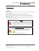
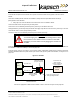
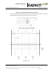
Install the power cords for the primary and secondary PSMs. Appropriate lightning/surge protection equipment
should be installed between the power mains input and the earth ground system at the Reader, see Figure 5-2 on
page 154.
Figure 5-2: AC Mains
6 ft. power cord
PSM
primary
Reader enclosure
PSM
secondary
POWER
MAINS
6 ft. power cord
duplex receptacle
supplied by system
integrator
Power mains and
cable to Reader
enclosure supplied by
system integrator
lightning surge
suppressor supplied
by system integrator
Earth ground system as per
“NEC grounding electrode”
MPR2
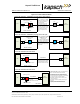
Connect the appropriate cables from the Reader to the LC as shown in Figure 5-3 on page 155.