
Operations and Maintenance Manual


_
JANUS
®
Multi-Protocol Reader 2.4 Maintenance Instructions
Confidential UM 360467-110 Revision: B Page 153 of 247
© Kapsch TrafficCom Canada Inc. 2021
All information contained herein is proprietary to, and may only be used with express, written permission from, Kapsch TrafficCom Canada Inc.
FILE: UM 360467-110 REV B3 MPR 2.4 CLEAN.DOCX 03/02/2021 1:01
Kapsch TrafficCom
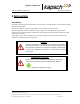
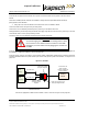
Figure 5-1: Earth Ground System (with recommended lightning protectors shown)
Note: The toll plaza installation may not have a NEMA 4 enclosure. The earth ground system and all other
ground connections to Reader components at the toll plaza are identical to those shown in the figure below.
Lightning protectors
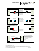
Note: It is the system integrator’s responsibility to determine the necessity of installing lightning/surge
protection equipment between the data inputs and the earth ground system at the Lane Controller (LC).
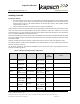
Table 5-1: Locations for the Installation of Lightning Protectors
Location required
Schematic Figure number
In-line with antenna RF feed
Figure 5-1: Earth Ground System (with recommended lightning protectors
shown), page 153
PSM power
Figure 5-2: AC Mains, page 154
LC Data inputs
Figure 5-3: LC Data Cable installation, page 155
ESM power
Figure 5-11: Synchronization circuit schematic for three Readers, page 166
Synchronization circuit
Figure 5-11: Synchronization circuit schematic for three Readers, page 166
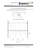
Installing the Reader hardware
Prerequisites: The Reader cabinet is commissioned and the earth ground system has been installed as per IEEE
142-2007, see the earth ground system on page 152.
EIA 19 in.
rack
Ground bar and clamp(s) are bonded to building/site
elements (if available) as per IEEE 142-2007, otherwise
the ground bar and clamp(s) are bonded to a grounding
electrode installed as per NEC.
AC Mains
(to PSMs and
ESMs)
AWG 10
AWG 8
Reader
Chassis
ground strap braid wire
RF
feedline
Lightning Protectors
LC data
cables
Sync
circuit
Reader enclosure
(NEMA 4)