
Operations and Maintenance Manual

_
JANUS
®
Multi-Protocol Reader 2.4 Maintenance Instructions
Confidential UM 360467-110 Revision: B Page 146 of 247
© Kapsch TrafficCom Canada Inc. 2021
All information contained herein is proprietary to, and may only be used with express, written permission from, Kapsch TrafficCom Canada Inc.
FILE: UM 360467-110 REV B3 MPR 2.4 CLEAN.DOCX 03/02/2021 1:01
Kapsch TrafficCom
Synchronization delay
Synchronization delay indicates how long the reader holds its sync driver low after synchronization has
occurred. This feature is used to calibrate out cable length delays.
If the reader detects that the sync bus is driven high prior to the expiry of this delay, the reader exits delay
mode and performs one of the following actions.
• Sets its driver high and falls into synchronization frame start delay if programmed
• Sets its driver high and begins firing its multi-protocol tag acquisition sequence.
Synchronization frame start delay
Synchronization frame start delay programs how long the Reader waits after Reader-to-Reader sync has
occurred. Its internal driver is set to a high state before firing the next frame and/or multi-protocol tag
acquisition sequence.
Sync recovery time
Sync recovery time is a programmable variable that indicates how long the reader searches/waits for
synchronization on the reader network before firing its multi-protocol tag acquisition sequence. It is
recommended that this value be programmed at least 125% of the total multi-protocol tag acquisition
sequence.
If the reader detects that the sync bus is driven high prior to the expiry of this time, the reader exits recovery
mode, sets its driver high and begins firing its multi-protocol tag acquisition sequence.
Sync recovery attempt limit:
Sync recovery attempt limit is used to indicate how many Sync Recovery Time periods must expire before the
Reader no longer searches/waits for synchronization before firing its tag acquisition sequence independent of
the reader network. A loss of reader synchronization message will be transmitted via the lane controller
interface.
If this limit is programmed with a zero (0) value, the Reader will always wait for Sync Recovery Time to expire
before firing its sequence.
Sync-on-skipped-sync frame
Sync-on-skipped-sync frame is used when more than 3 protocols are selected in the multi-protocol tag
acquisition sequence. A two sequences-skip is used to indicate where the sequence starts.
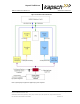
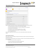
How Reader synchronization operates at the toll location
After interrogating all of the assigned MRFM-S slots in the rack, each Reader will provide a ‘sync ready’ signal on
its SPM terminal block. Only when the configuration parameter Enable Reader –to-Reader Sync checkbox is
selected under the SYNC panel does synchronization occur. See page 167 for instruction how to enable sync.
As busy Readers become ready they will not send any more RF trigger signals until the sync bus indicates that all
Readers are ready. Once the last Reader in the network generates its ready signal, all Readers on the sync bus
simultaneously generate OBU trigger pulses starting with the RF module in slot 1. This can be seen in the truth
table shown below for synchronization circuit consisting of two Readers.