
Operations and Maintenance Manual

_
JANUS
®
Multi-Protocol Reader 2.4 Maintenance Instructions
Confidential UM 360467-110 Revision: B Page 143 of 247
© Kapsch TrafficCom Canada Inc. 2021
All information contained herein is proprietary to, and may only be used with express, written permission from, Kapsch TrafficCom Canada Inc.
FILE: UM 360467-110 REV B3 MPR 2.4 CLEAN.DOCX 03/02/2021 1:01
Kapsch TrafficCom
two other Readers, saves Reader configuration parameters to the primary and secondary CFM, manages the
OBU Account Status file, and keeps log files for OBU transactions, system events, and trouble reports.
For a description of the ethernet interface protocol and file formats exchanged between a Lane Controller and a
Reader, refer to ICD 360467-121.
Channel Group Controller Module (CGC)
The CGC is used as a scheduler, message buffer, and a controller. It schedules when the MRFM-S operates,
routes configuration data from the MC to the MRFM-S, and routes message data from the MRFM-S to the MC.
It also manages timing synchronization between readers and CTMs.
Configuration Module (CFM)
The CFM is a field replaceable PWA board. These non-volatile memory cards store the Reader configuration file.
They are field-replaceable without using any tools.
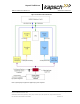
Distribution Module (DSM)
The DSM provides interconnections between the plug-in modules in the Reader rack. It is not field-replaceable.
The DSM:
• Provides locations for all plug-in Reader modules and the Lane Kit RF modules
• Distributes DC power from the PSMs to the necessary modules in the Reader rack
• Carries RF data and control signals between primary and secondary CTMs and all MRFM-Ss
• Carries synchronization and redundancy mode signals between primary and secondary CTMs and the SPM
• Carries data between primary and secondary CTMs and primary and secondary CFMs
• Carries data between primary and secondary CTMs and primary and secondary LPMs
Multiple reader synchronization
Readers must be synchronized under the following conditions.
• If they have overlapping capture zones,
• If they are connected in an IR network
• If Reader-to-Reader RF interference is present.
Sync is recommended for installations that are less than 600 feet apart. For distances above this up to the sync
cable maximum distance (1500 ft) tests for in-band interference should be carried out to ensure no Reader-
Reader interference occurs.