
Operations and Maintenance Manual


_
JANUS
®
Multi-Protocol Reader 2.4 Maintenance Instructions
Confidential UM 360467-110 Revision: B Page 140 of 247
© Kapsch TrafficCom Canada Inc. 2021
All information contained herein is proprietary to, and may only be used with express, written permission from, Kapsch TrafficCom Canada Inc.
FILE: UM 360467-110 REV B3 MPR 2.4 CLEAN.DOCX 03/02/2021 1:01
Kapsch TrafficCom
Multi-protocol RF Module Smart
The Multi-protocol RF Module Smart (MRFM-S) and Multi-protocol RF Module Smart Plus (MRFM-S Plus) can
handle multiple passive tag protocols; 6B (ISO 18000-6 Type B), 6C (ISO 18000-6 Type C), ATA (10374/ATA/AAR
S-918), SeGo as well as the active protocol TDM.
The MRFM-S design includes a software command for adjusting the transmitter peak output power.
ATTENTION: When installing or replacing an RF module, the lane should be re-tuned. A reader can only
contain either MRFM-S or MRFM-S Plus modules but not both.
The RF Module transmits recovered OBU data as messages to the CGC. After the messages are processed by the
CTM, a transaction message is normally sent to the LC.
Power Supply Module (PSM)
The PSM AC mains power requirement is 95-230VAC (60Hz+/-2 Hz) at 10A max input current.
The PSM is field replaceable and provides:
• A power switch and a 10A fuse
• +5V and +15V DC power outputs
• +5V and +15V LEDs to indicate power supply output status
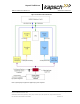
In the redundant configuration, both the primary and secondary PSMs are normally powered on. The primary
PSM provides power to the primary CTM and the secondary PSM provides power to the secondary CTM. Both
PSMs share the RF module load.
In the event of failure of one PSM, an automatic switchover will occur and the redundant PSM provides all the
power for the RF module load.
The PSMs are not interchangeable. The Primary and Secondary power supplies have different part numbers; a
result of being physical mirror images of each other.
Each PSM has a mains power fuse on the front panel: Time lag, 10 A @ 250 V, UL rated.
The power supply distribution is shown in Figure 4-1, page 141.