
Operations and Maintenance Manual

_
JANUS
®
Multi-Protocol Reader 2.4 Maintenance Instructions
Confidential UM 360467-110 Revision: B Page 139 of 247
© Kapsch TrafficCom Canada Inc. 2021
All information contained herein is proprietary to, and may only be used with express, written permission from, Kapsch TrafficCom Canada Inc.
FILE: UM 360467-110 REV B3 MPR 2.4 CLEAN.DOCX 03/02/2021 1:01
Kapsch TrafficCom
4. THEORY OF OPERATIONS
This section offers a more detailed overview of the Reader components than the introductory overview
provided in Overview Section 2 page 23.
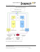
Multi-protocol Readers can communicate with both active and passive OBUs. The Reader uses a combination of
Time Division Multiplexed (TDM) and Frequency Division Multiplexed (FDM) periods to read active and passive
OBUs respectively.
Each MRFM-S or MRFM-S Plus and antenna pair, referred to as a channel, creates an RF capture zone on the
roadway. The antennas are usually situated to create overlapping capture zones between channels. One reader
can support up to 8 channels. When required, multiple readers can be synced together to support additional
channels.
The reader processes the OBU information and provides transaction reports to the Lane Controller interfaces.
When required, the reader can write data to the OBU.
Active OBUs
Active OBUs are battery powered and transmit a signal to the Reader antennas. As a vehicle equipped with an
active OBU approaches a toll plaza, the OBU receives a trigger signal from the Tx antenna. The OBU then starts
transmitting data, which is received by the Rx antenna.
The MRFM-S or MRFM-S Plus decodes the active OBU signal and passes the data to the CTM, which processes
and logs the OBU data and then sends the information to the Lane Controllers (LCs). The Reader may also send
data back to the active OBUs, such as an updated toll account balance.
Passive OBUs
Passive tags are not battery powered and cannot transmit a signal. As a vehicle equipped with a passive OBU
approaches the antenna, the OBU receives a transmit signal from the antenna. This signal is then reflected from
the passive OBU back to the antenna. The reflected signal is uniquely modulated by each passive OBU, allowing
the OBU to be identified.
The MRFM-S or MRFM-S Plus decodes the passive OBU signal and passes the data to the CTM which processes
and logs the OBU data and then sends the information to the Lane Controllers (LCs).
Capture zones
The capture zone is the area of antenna RF coverage. An antenna can communicate with an OBU once the OBU
enters the antenna’s capture zone. These capture zones and the number of antennas required per lane varies
depending on the site and/or lane configuration.
Note: Where Kapsch is responsible installation and tuning, installation on sites and lanes is assessed by
Kapsch Personnel prior to deployment in order to validate customer expectations and performance.