
Operations and Maintenance Manual
_
JANUS
®
Multi-Protocol Reader Ver. 2: Appendix
Confidential UM 360450-210 Revision C Page 217 of 288
© Kapsch TrafficCom Canada Inc. 2014
These drawings and specifications contain confidential and proprietary information and are the property of Kapsch TrafficCom Canada Inc. and are issued in strict
confidence and will be kept confidential and used solely for the purpose intended and for no other purpose and shall not be transmitted, reproduced, copied, and/or
used as the basis for manufacture or sale of apparatus unless otherwise agreed to in writing by Kapsch TrafficCom Canada Inc.
FILE: UM 360450-210 REV C JANUS MPR2 OPERATOR-MAINTENANCE MANUAL.DOCX 08/17/2015 11:42
Kapsch TrafficCom
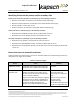
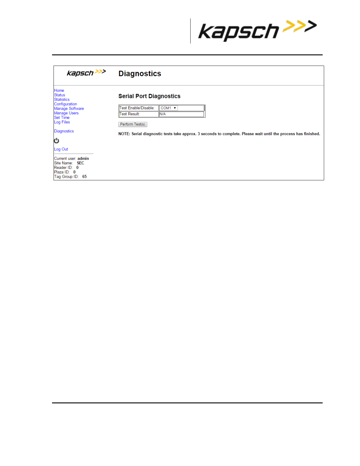
5. Select the LPM COM port from the Test Enable/Disable drop-down box.
6. Click the Perform Test(s) button.
Result: The test result displays.
7. If the test passes, the LPM COM port is functional.
8. If the test fails, ensure the correct loop-back connector was used, then, replace the CTM and repeat steps
4 and 6.
9. If the test fails again, record under what conditions the LPM failed.
10. Replace the LPM.
11. Return failed LPM under the RMA agreement.
Testing the Synchronization Circuit
This first part of this test checks the functionality of one Reader’s SPM. The second part of this test
checks the Synchronization wiring from one Reader’s SPM to the synchronization circuit terminal block
Prerequisites:
At least one RF module installed in the Reader
Both Primary and Secondary CTMs are configured the same
Synchronization enabled
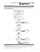
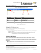
Testing the SPM and CTM
1. Disconnect the Synchronization circuit wiring from the SPM terminal block
2. Using two short jumper wires connect Tx+ to Rx+ and Tx- to Rx- on the SPM terminal block, leaving the GND
terminals unconnected (see SPM terminal block connections, page 261).
3. If the SYNC LED on both CTM’s illuminates solid green, the SPM and CTM’s are functioning properly.
4. Reconnect the synchronization circuit to the SPM terminal block.