
Operations and Maintenance Manual

_
JANUS
®
Multi-Protocol Reader Ver. 2: Maintenance Instructions
Confidential UM 360450-210 Revision C Page 173 of 288
© Kapsch TrafficCom Canada Inc. 2014
These drawings and specifications contain confidential and proprietary information and are the property of Kapsch TrafficCom Canada Inc. and are issued in strict
confidence and will be kept confidential and used solely for the purpose intended and for no other purpose and shall not be transmitted, reproduced, copied, and/or
used as the basis for manufacture or sale of apparatus unless otherwise agreed to in writing by Kapsch TrafficCom Canada Inc.
FILE: UM 360450-210 REV C JANUS MPR2 OPERATOR-MAINTENANCE MANUAL.DOCX 08/17/2015 11:42
Kapsch TrafficCom
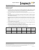
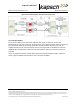
For Bi-Static Operation
See Figure 5-6: RF Cable Installation Schematic Bi-Static Operation
1. Using a 10in-lb torque wrench, connect the first RF feedline cable to the Circulator (Port 1). Using self-
amalgamating tape, wrap the connection to ensure water cannot enter.
2. Using a 10in-lb torque wrench, connect the second RF feedline cable to the Circulator (Port 3). Using
self- amalgamating tape, wrap the connection to ensure water cannot enter.
3. Using a 10in-lb torque wrench, connect a third (3.0 foot long) RF feedline cable to the Circulator (Port 2).
Using self-amalgamating tape, wrap the connection to ensure water cannot enter.
4. Attach the N-Type male connector to the antenna end of the third (3.0 foot long) RF feedline cable.
Firmly crimp the male connector.
5. Using a 10in-lb torque wrench, connect the other end of the third (3.0 foot long) RF feedline cable that is
connected to Port 2 of the Circulator, to the antenna. Using self-amalgamating tape, wrap the connection
to ensure water cannot enter.
6. Attach the N-Type female connector to the reader end of the first RF feedline cable. Firmly crimp the
female connector.
7. Using a 10in-lb torque wrench, connect the other end of the first RF Feedline cable that is connected to
Port 1 of the Circulator, to the RF Adaptor Cable (800125-001), that will be connected to the “Antenna”
Port of the MRFMS.
8. Attach the N-Type female connector ) to the reader end of the second RF feedline cable. Firmly crimp
the female connector.
9. Using a 10in-lb torque wrench, connect the other end of the second RF Feedline cable that is connected
to Port 3 of the Circulator, to the RF Adaptor Cable (800125-001), that will be connected to the “RX” Port
of the MRFMS.
10. Using an SMA wrench, connect each RF Adapter Cable(s) (800125-001) SMA connector to the assigned
MRFM-S module port(s).
11. Tie all RF Adapter cables neatly and label both ends of each adapter cable, using marker tie wraps.
12. Secure the service loop portion of the feedline to the antenna-mounting bracket using the tie wraps. Do
not severely bend or kink the RF feedline cable.
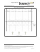
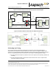
Note: For a TDM and/or 6C only protocol configuration (i.e., no other passive protocols), the Circulator
can be located in the cabinet with the reader and one RF feedline cable is connected between port 2 of
the Circulator and the antenna. Ports 1 and 3 of the circulator are then connected to the RF modules
using the RF Adaptor Cables (800125-001); see Figure 5-8: RF Cable Installation Schematic Bi-Static
TDM/6C Only Operation