
Operations and Maintenance Manual
_
JANUS
®
Multi-Protocol Reader Ver. 2: Maintenance Instructions
Confidential UM 360450-210 Revision C Page 172 of 288
© Kapsch TrafficCom Canada Inc. 2014
These drawings and specifications contain confidential and proprietary information and are the property of Kapsch TrafficCom Canada Inc. and are issued in strict
confidence and will be kept confidential and used solely for the purpose intended and for no other purpose and shall not be transmitted, reproduced, copied, and/or
used as the basis for manufacture or sale of apparatus unless otherwise agreed to in writing by Kapsch TrafficCom Canada Inc.
FILE: UM 360450-210 REV C JANUS MPR2 OPERATOR-MAINTENANCE MANUAL.DOCX 08/17/2015 11:42
Kapsch TrafficCom
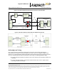
correct lane). There may also be some reduction in the read performance for passive
protocols.
If the physical lane width exceeds 15 ft, the lane should be treated as a multi-lane free flow
configuration and multiple lane kits used per lane.
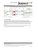
Where multiple readers are on a site, the following additional guidelines apply:
The readers must be synchronized and running the same configuration.
The same FDM channel frequency should not be used on adjacent lanes (including straddle
and shoulder).
The same active channel from two (2) synchronized readers should not be used on adjacent
lanes (including straddle and shoulder).
Installing the MRFM-S Modules
CAUTION:
To avoid damaging the modules, ensure that alignment of both
the connector on the module and the connector on the DSM
(back plane) is correct before securely plugging the module into
the DSM.
1. Insert the required number of MRFM-S Modules into the Reader and secure in place.
2. Label the front panel of each MRFM-S Module with the corresponding lane number and antenna type.
Installing the RF cables
CAUTION:
Excessive bending or kinking can damage the RF feedline cables. Do not
excessively bend or kink the RF feedline cables while fishing them through
the rigid conduit from the antenna to the Reader enclosure.
1. Place the RF feedline cable(s) in position. Use an appropriate cable type (coaxial or Heliax) to ensure the
RF feedline cable does not produce a signal loss greater than permitted, see section 8 RF Cable
Specification. Use flexible cable (LMR400 preferred) for the short feedline cable between the circulator
and the antenna
2. Using tie wraps, create a service loop of 6 feet at both ends of the RF feedline cable(s). Trim the excess
cable length.
3. Install spiral wraps on the RF feedline cable(s) where necessary to protect it from abrasion.
4. Using marker tie wraps and label sets, label the Reader end of each RF feedline (ex. TX Lane 1 or RX
Lane 1), each antenna RF feedline (ex. Tx lane 1 or Rx lane 1).
5. Attach the N-Type male connector to the antenna end of the RF feedline cable(s) . Firmly crimp the
male connector.