
Operations and Maintenance Manual


_
JANUS
®
Multi-Protocol Reader Ver. 2: Maintenance Instructions
Confidential UM 360450-210 Revision C Page 155 of 288
© Kapsch TrafficCom Canada Inc. 2014
These drawings and specifications contain confidential and proprietary information and are the property of Kapsch TrafficCom Canada Inc. and are issued in strict
confidence and will be kept confidential and used solely for the purpose intended and for no other purpose and shall not be transmitted, reproduced, copied, and/or
used as the basis for manufacture or sale of apparatus unless otherwise agreed to in writing by Kapsch TrafficCom Canada Inc.
FILE: UM 360450-210 REV C JANUS MPR2 OPERATOR-MAINTENANCE MANUAL.DOCX 08/17/2015 11:42
Kapsch TrafficCom
+5V and +15V DC power outputs
+5V and +15V LEDs to indicate power supply output status
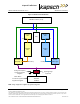
In the redundant configuration, both the primary and secondary PSMs are normally powered on. The
primary PSM provides power to the primary CTM and the secondary PSM provides power to the
secondary CTM. Both PSMs share the RF module load.
In the event of failure of one PSM, an automatic switchover will occur and the redundant PSM provides
all the power for the RF module load.
The PSMs are not interchangeable. The Primary and Secondary power supplies have different part
numbers; a result of being physical mirror images of each other.
Each PSM has a mains power fuse on the front panel: Time lag, 10 A @ 250 V, UL rated.
The power supply distribution is shown in Figure 4-1, page 156.