
Operations and Maintenance Manual


_
JANUS
®
Multi-Protocol Reader Ver. 2: Maintenance Instructions
Confidential UM 360463-202: A12 (Draft) Page 149 of 291
© Kapsch TrafficCom Canada Inc. 2013
These drawings and specifications contain confidential and proprietary information and are the property of Kapsch TrafficCom Canada Inc. and are issued in strict
confidence and will be kept confidential and used solely for the purpose intended and for no other purpose and shall not be transmitted, reproduced, copied, and/or
used as the basis for manufacture or sale of apparatus unless otherwise agreed to in writing by Kapsch TrafficCom Canada Inc.
FILE: MPR2_OPERATIONS_AND_MAINTENANCE-MANUAL_REV A12.DOCX 05/08/2014 11:24
Kapsch TrafficCom
Installing a Lane Kit
Installing an Antenna
1. The antenna mounts on a frame using 2-inch diameter galvanized pipe clamps. Position the center
antenna at lane center of the defined lane. For wide ORT applications, the straddle antenna must be at
the midpoint between the left and right antennas. Orient the weep holes down, such that the radome is
facing oncoming traffic.
2. Using a tilt meter, measure the road pitch and cross lane slope directly under each IAG antenna. Record
the results.
3. Using a tilt meter, align each antenna plate to the tilt angle specified in Table 5-2, in relation to the road
pitch measured in step 2 (e.g., If the road pitch is 2 degrees. and the antenna tilt must be 15 degrees,
mount the antenna at 17 degrees.)
4. Ensure that the height of the antenna’s lower edge as tilted falls within the height range given Table 5-2.
Please contact Kapsch Service when considering mounting the antennas outside the specified heights.
5. Adjust the roll angle of the antenna equal to 0 degrees with respect to the cross lane slope obtained in
step 2.
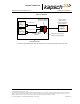
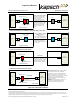
6. For TDM only protocol, the antenna installation may be all antennas (IAG 1 or IAG 2 or IAG 3) inline
across the roadway as shown in Figure 5-3
7. For TDM protocol, and/or ISO18000-6C protocol (read only) only, the antenna installation may be all
antennas IAG 3 only) inline across the roadway as shown in Figure 5-3.
8. For all passive protocols (other than ISO18000-6C read only) the antenna installation must be all
antennas (IAG 3 only) staggered across the roadway as shown in Figure 5-3.
Table 5-2 Antenna mounting for the IAG 3 antenna and lane configuration
Antenna
Application
Lane Width
Height
Tilt (off
horizontal)
IAG-3
ORT or Plaza
12 ft.
17 ft. ±1 ft.
10 deg.
IAG-1
ORT or Plaza
12 ft.
16 ft. ±1 ft.
10 deg.