
User's Manual

_
JANUS
®
Multi-Protocol Reader Ver. 2: Maintenance Instructions
Confidential UM 360450-210: A7 Page 200 of 282
© Kapsch TrafficCom Canada Inc. 2013
These drawings and specifications contain confidential and proprietary information and are the property of Kapsch TrafficCom Canada Inc. and are issued in strict
confidence and will be kept confidential and used solely for the purpose intended and for no other purpose and shall not be transmitted, reproduced, copied, and/or
used as the basis for manufacture or sale of apparatus unless otherwise agreed to in writing by Kapsch TrafficCom Canada Inc.
FILE: UM 360450-210 OPERATIONS AND MAINTENANCE MANUAL.DOCX 10/31/2013 7:56
Kapsch TrafficCom
Testing the SPM and CTM
1. Disconnect the Synchronization circuit wiring from the SPM terminal block
2. Using two short jumper wires connect Tx+ to Rx+ and Tx- to Rx- on the SPM terminal block, leaving the GND
terminals unconnected (see SPM terminal block connections, page 259).
3. If the SYNC LED on both CTM’s illuminates solid green, the SPM and CTM’s are functioning properly.
4. Reconnect the synchronization circuit to the SPM terminal block.
Testing the Synchronization hub cabling
1. If the SYNC LED on the CTM does not illuminate solid green with a functional SPM and CTM connected to the
Synchronization circuit, the problem is with the wiring between the SPM and the synchronization hub terminal
block.
Testing the MRFM-S slots
The following test is to verify that all MRFM-S slots in the upper portion of the Reader rack are
functional.
Prerequisites: Connect the service laptop to to access the CTM web interface. Refer to Connecting a
service laptop to the Reader, page 40. One functional MRFM-S is installed in the RF slot 1 of the
Reader rack.
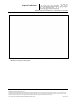
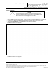
1. Select the Configuration link on the left side panel.
Result: The following screen appears.