
User's Manual

_
JANUS
®
Multi-Protocol Reader Ver. 2: Maintenance Instructions
Confidential UM 360450-210: A7 Page 183 of 282
© Kapsch TrafficCom Canada Inc. 2013
These drawings and specifications contain confidential and proprietary information and are the property of Kapsch TrafficCom Canada Inc. and are issued in strict
confidence and will be kept confidential and used solely for the purpose intended and for no other purpose and shall not be transmitted, reproduced, copied, and/or
used as the basis for manufacture or sale of apparatus unless otherwise agreed to in writing by Kapsch TrafficCom Canada Inc.
FILE: UM 360450-210 OPERATIONS AND MAINTENANCE MANUAL.DOCX 10/31/2013 7:56
Kapsch TrafficCom
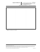
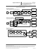
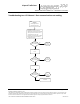
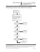
Figure 6-1: Signal Flow Diagrams
Reader components in sync signal generation
path. After sync signal detection by the CTM, the
shaded components are in the sync usage path.
CTM
LANE
CONTROLLER
HOST
COMPUTER
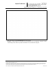
Signal Flow Diagram:
Tag Transaction in one dedicated lane
MRFMSANTENNATAG DSM DSM LPM
Reader components in transaction signal path.
CTM
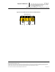
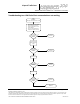
Signal Flow Diagram:
Tag Transaction in ORT
MRFMS ANTENNA
TAG
DSM LPM
Reader components in
transaction signal path.
MRFMS
MRFMS
ANTENNA
ANTENNA
CTM
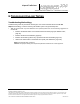
Signal Flow Diagram:
Synchronization
MRFMS DSM DSM
SPM
STAR SYNC HUB
(TERMINAL
BLOCK)
READER 2
READER 3
READER 4
INTERNET LAN
LANE
CONTROLLER
HOST
COMPUTER
INTERNET LAN
CFM
DSM
CFM
INTER-READER NETWORK
(if voting on lane assignment)