
User's Manual

_
JANUS
®
Multi-Protocol Reader Ver. 2: Maintenance Instructions
Confidential UM 360450-210: A7 Page 149 of 282
© Kapsch TrafficCom Canada Inc. 2013
These drawings and specifications contain confidential and proprietary information and are the property of Kapsch TrafficCom Canada Inc. and are issued in strict
confidence and will be kept confidential and used solely for the purpose intended and for no other purpose and shall not be transmitted, reproduced, copied, and/or
used as the basis for manufacture or sale of apparatus unless otherwise agreed to in writing by Kapsch TrafficCom Canada Inc.
FILE: UM 360450-210 OPERATIONS AND MAINTENANCE MANUAL.DOCX 10/31/2013 7:56
Kapsch TrafficCom
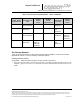
The same FDM channel frequency should not be used on adjacent lanes (incl straddle and
shoulder).
The same TDM channel from 2 synchronized readers should not be used on adjacent lanes (incl
straddle and shoulder).
The TX attenuation should be adjusted to obtain capture zones nominally 8-12 ft along direction
of vehicle traffic.
When installing or replacing a MRFM-S, RF cables, Circulator, or antenna, the
lane must be retuned. The Synchronization circuit
Reader synchronization ensures antennas from different Readers do not attempt to communicate
simultaneously with the same on-board unit (OBU). The synchronization circuit connects SPMs
together in a star network. The CTM does the synchronization of the RF module interrogation.
Prerequisites: Sync hub terminal block mounted in a location central to the Readers. The exact
location of this terminal block should be marked on a site map to aid system maintenance.
Readers arranged so that no Reader is farther than 1500 feet from the sync hub terminal block
Readers arranged so that the total synchronization network cable length is no greater than 2000
feet
No more than six (6) Readers in the synchronization circuit
Note: It is recommended that each synchronization cable have two or more spare conductors to
support future service repair calls.
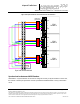
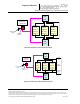
Installing a synchronization circuit
1. Connect the Readers to the Sync hub terminal block as in Figure 0-8 on page 152.
Attention: Ensure that cables do not connect from the GND terminal on the SPM to the Sync hub
terminal block, as this can create a ground loop and affect synchronization performance.
Note: Before you continue, you will need to gain access to the CTM web Interface through a computer or
service laptop connected to the Ethernet 1 port or the USB port of the Reader. See the following procedures
for more information.
Connecting a service laptop to the Reader on page 40.
Changing the service laptop IP address on page 40.
Testing the connection to the reader on page 40.
Accessing the CTM web interface on page 40.
2. Select the Configuration link on the left side panel.
Result: The following screen appears.