
User's Manual

_
JANUS
®
Multi-Protocol Reader Ver. 2: Maintenance Instructions
Confidential UM 360450-210: A7 Page 146 of 282
© Kapsch TrafficCom Canada Inc. 2013
These drawings and specifications contain confidential and proprietary information and are the property of Kapsch TrafficCom Canada Inc. and are issued in strict
confidence and will be kept confidential and used solely for the purpose intended and for no other purpose and shall not be transmitted, reproduced, copied, and/or
used as the basis for manufacture or sale of apparatus unless otherwise agreed to in writing by Kapsch TrafficCom Canada Inc.
FILE: UM 360450-210 OPERATIONS AND MAINTENANCE MANUAL.DOCX 10/31/2013 7:56
Kapsch TrafficCom
Installing the MRFM-S Modules
CAUTION:
To avoid damaging the modules, ensure that alignment of both
the connector on the module and the connector on the DSM
(back plane) is correct before securely plugging the module into
the DSM.
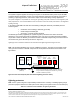
1. Insert the required number of MRFM-S Modules into the Reader and secure in place.
Label the front panel of each MRFM-S Module with the corresponding lane number and antenna type.
Installing the RF cables
CAUTION:
Excessive bending or kinking can damage the RF feedline cables. Do not
excessively bend or kink the RF feedline cables while fishing them through
the rigid conduit from the antenna to the Reader enclosure.
2. Place the RF feedline cable(s) in position. Use an appropriate cable type (coaxial or Heliax) to ensure the
cable does not produce a signal loss of more than 4dB in the main RF feedline cable. Use flexible cable
(LMR400 preferred) for the short feedline cable between the circulator and the antenna
3. Using tie wraps, create a service loop of 6 feet at both ends of the RF feedline cable(s). Trim the excess cable
length.
4. Install spiral wraps on the RF feedline cable(s) where necessary to protect it from abrasion.
5. Using marker tie wraps and label sets, label the Reader end of each RF feedline (ex. TX Lane 1 or RX Lane
1), each antenna RF feedline (ex. Tx lane 1 or Rx lane 1).
6. Attach the N-Type male connector to the antenna end of the RF feedline cable(s) . Firmly crimp the male
connector.
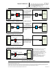
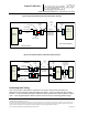
For Mono-Static Operation only (Not Currently Supported) . See Figure 0-3
1. Using a 10in-lb torque wrench, connect the RF feedline cable to the antenna. Using self-amalgamating tape,
wrap the connection to ensure water cannot enter.
2. Attach the N-Type female connector to the Reader end of the feedline cable . Firmly crimp the female
connector.
3. Using a 10in-lb torque wrench, connect the RF feedline from the antenna to the RF adapter cable (800125-
001).
Note: A lightning protector should be installed between the RF adapter cable and the feedline cable.
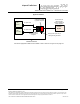
For Bi-Static Operation Only. See Figure 0-3
1. Using a 10in-lb torque wrench, connect the first RF feedline cable to the Circulator (Port 1). Using self-
amalgamating tape, wrap the connection to ensure water cannot enter.
2. Using a 10in-lb torque wrench, connect the second RF feedline cable to the Circulator (Port 3). Using self-
amalgamating tape, wrap the connection to ensure water cannot enter.
3. Using a 10in-lb torque wrench, connect a third (3.0 foot long) RF feedline cable to the Circulator (Port 2).
Using self-amalgamating tape, wrap the connection to ensure water cannot enter.