
User's Manual

_
JANUS
®
Multi-Protocol Reader Ver. 2: Maintenance Instructions
Confidential UM 360450-210: A7 Page 141 of 282
© Kapsch TrafficCom Canada Inc. 2013
These drawings and specifications contain confidential and proprietary information and are the property of Kapsch TrafficCom Canada Inc. and are issued in strict
confidence and will be kept confidential and used solely for the purpose intended and for no other purpose and shall not be transmitted, reproduced, copied, and/or
used as the basis for manufacture or sale of apparatus unless otherwise agreed to in writing by Kapsch TrafficCom Canada Inc.
FILE: UM 360450-210 OPERATIONS AND MAINTENANCE MANUAL.DOCX 10/31/2013 7:56
Kapsch TrafficCom
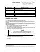
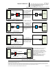
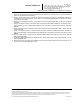
Location required
Schematic Figure number
In-line with antenna RF feed
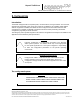
Figure 0-1: Earth Ground System (with recommended lightning
protectors shown), page 140
PSM power
Figure 0-2 AC Mains, page 142
LC Data inputs
Figure 0-3: LC Data Cable Installation, page 143
ESM power
Figure 0-9: Schematic of a three-Reader IR network, page 158
Synchronization circuit
Figure 0-8: Synchronization circuit schematic for three Readers, page
152
Installing the Reader hardware
Prerequisites: The Reader cabinet is commissioned and the earth ground system has been installed
as per IEEE 142-2007 (see The earth ground system on page 139).
Install the AC receptacle for the Reader mains power connections within three (3) feet of the front of
the Reader.
Note: When handling Reader modules and hardware, always follow accepted Electrostatic Discharge
(ESD) practices and standards.
1. Using clip nuts, mount the Reader in the EIA 19-inch rack in a NEMA 4 cabinet.
2. Connect the EIA 19-inch rack ground lug to earth ground:
3. Connect one end of a braided ground strap to the ground lug on the EIA 19-inch rack.
4. Neatly position the ground strap along the Reader and apply a light film of tuner lube to the ground lug on the
rear of the Reader rack to ensure good grounding contact.
5. Secure the other end of the braided ground strap to the Reader ground lug.
CAUTION:
To avoid damaging the modules, ensure that alignment of both
the connector on the module and the connector on the DSM
(back plane) is correct before securely plugging the module into
the DSM.
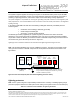
6. Install the Reader modules in the Reader, ensuring the modules seat properly in their sockets. The installation
of the MRFM-S is outlined in Installing a Lane Kit on page 144.
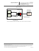
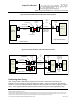
7. Install the power cords for the primary and secondary PSMs. Appropriate lightning/surge protection equipment
should be installed between the power mains input and the earth ground system at the Reader (see Figure
0-2 on page 142).