
User Instructions

HOTPass ® Interior Transponder
Mounting
3M
™
Dual Lock
™
HOTPass
®
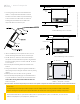
Transponder - Rear View
rear view
mirror post
orientation arrow
2 in. maximum
rooine
Alternate Mounting Location - Front View
rooine
2 in. maximum
rear view mirror post
Preferred Mounting Location - Front View
orientation
arrow
©Kapsch TracCom Canada Inc. All rights reserved. Subject to alteration without notice
801850-022 Rev A4
2. If there is insucient space in the preferred location, select an
alternate mounting location beside the rear view mirror post.
3. Two 3M
™
Dual Lock
™
fasteners on the back of the HOTPass
®
transponder are used to mount the transponder to the windshield.
Prepare the mounting location in accordance with 3M
™
document
70 - 0709 -4029-4.
4. Remove the protective backing from the two 3M
™
Dual Lock
™
fasteners.
5. Firmly press the HOTPass
®
transponder against the windshield in
the mounting location, ensuring the orientation arrows are pointing
skyward.
6. Maintain pressure for 15 seconds to ensure a good bond.
7. Remove the transponder by lifting any corner with sucient force
to separate the Dual Lock
™
fasteners. Do not reuse the Dual Lock
™
fasteners after removing them from the windshield. Obtain new
fasteners as required.
1. Select a mounting location on the front windshield. The
HOTPass
®
more that 2 in. from the rooine. The preferred mounting
location is between the rooine and the rear view mirror
transponder and the rear view mirror post.
Kapsch TracCom North America | 8201 Greensboro Drive, Suite 1002 | McLean, VA 22102 | Phone +1 703 885 1976 |
Fax +1 703 790 9100
E-Mail ktc.ca.info@kapsch.net | ktc.na@kapsch.net | www.kapsch.net
Kapsch Group
The Kapsch Group and its entities Kapsch TracCom, Kapsch CarrierCom and Kapsch BusinessCom are specialised in the future-oriented market
segments of Intelligent Transportation Systems (ITS) and Information and Communication Technology (ICT). Kapsch. Always one step ahead.
fasteners after removing them from the windshield. Obtain new
1/2 in. preferred
1/2 in. preferred
1/2 in. minimum
1/2 in. minimum.
1-1/2 in. maximum
transponder should be mounted 1/2 in. but no
mounting post, with a minimum of 1/2 in. between the
switch
FCC License Notice - This device complies with part 15 of the FCC rules. Operation is subject to the condition that this device does not cause harmful interference.