Trademarks IBM PC, 0OS/2, PS/2, EGA, and VGA are registered trademarks of international Business Machines Corporation. Intel, Pentium are trademarks of Intel Corporation. MS-DOS, Microsoft Windows, Windows NT and Microsoft Mouse are registered trademarks of Microsoft Corporation. Sound Blaster Pro is a trademark of Creative Labs, Inc. System Soft is a registered trademark of System Soft Corp. Other brand and product names are trademarks of their respective companies.
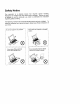
Safety Notice The computer is a delicate device that requires careful handling. Negligence or mistaken use may Cause Serious damage. Before you learn to operate or use this computer, you need to understand the instruction regarding safety handling. The following mentions the incorrect handling that is seriously inhibited. To keep the computer from being damaged. please keep these precautions in your mind. Do not Yarn off power in operation. Do not place the computer on unstable surface.
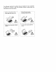
The following mentions the actions that are important for your computer. To keep your computer in the most excellent condition, please follow the instruction as much as possible. If there is unusual odor, heat or smoke, plug out the power cord. Plug out the parer cord in attaching peripheral devices. Follow the use instruction in taking airplane. Use the same brand of peripheral devices.
Conventions This manual uses the following conventions to describe, identify, and highlight terms and operating procedures. Text Conventions Text in boldface contains messages that are important for safe operation. Please read. Characters in boldface represent specific items or keys, e.g. Card Bus, Fn key. File names are presented in bold capitals, e.g. AN>0VMAKFIL /Pn.
Lighting Proper lighting and comfortable display viewing angle can reduce eye strain and muscle fatigue in your neck and shoulders. O Position the display to avoid glare or reflections from overhead lighting or outside sources of light. Keep the display screen clean and set the brightness and contrast to levels that allow you to see the screen clearly Position the display directly in front of you at a comfortable viewing distance. Adjust the display viewing angle to find the best position.
Table of Contents Chapter 1 : Getting Started Unpacking... Operating Environment Powering the System... AC Power Adapter. Battery Pack... Opening the LCD Cover. LED Indicators on the Leo Cover Top-Front View LCD Panel. Stereo Speakers .. Track pad and Buttons. Keyboard... Microphone System Status LED Indicators Power Button Rear View Right-Side View . Left-Side View 5.
Chapter 1 : Getting Started This chapter provides you with the short instruction of notebook computer system that will help you to get the basic understanding about the computer.
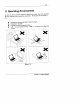
1-3 = Operating Environment As with any other precision electronic equipment, proper care and operation of your computer will prolong the use period. Make sure the computer is not: Exposed to excessively heat or direct sunlight. Shocked or vibrated. Exposed to strong magnetic fields. Left in a place where foreign matter or moisture may affect the system.
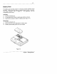
1-5 Battery Pack The battery pack provides power for continuous portable operation of the computer. When using the battery no external power source is required The actual operation time is related to the application and the configuration you're using. Inserting 1. Tum the computer over. 2. Fit the battery pack firmly at a slight angle into the computer. 3. install the four screws to fasten the battery pack (Figure 1-4). Removing 1. Turn the computer over. 2.
1-7 & Opening the LCD Cover Move the tats to the right to release the top cover. (Figure 1-5). Lift the top cover to reveal the LCD panel and keyboard (Figure 1-6). Adjust the LCD panel to a comfortable viewing angle. Press the power button to turn the system on or off {refer to Chapter 1, Top-Front View for more information of the power button).
= Top-Front View LCD Panel The computer provides you with a large LCD panel. Depending on the medal you have purchased, it can either be a 15.1" or 15.0" TFT flat panel The LCD panel is driven by a AGP bus video controller with 8 MB video memory. Stereo Speakers Twa built-in speakers provide clear stereo sound. Track pad and Buttons The pointing device features a sensitive glide pad for precise movements. It functions like a two-button mouse does.
AR P= Microphone LCD Panel Power Button Track pad and Buttes Status LED Indicators ~~ Figure 1-8 Chapter 1: Getting Started
External Monitor (CRT) Port This port is used for transmission of the display to an external monitor. Simultaneous display with the LCD panel is available. Dual PS/2 Type Ports @a\d A PS/2 type mouse and keyboard can be connected to the system using these ports. However, you cannot connect the same type of PS/2 devices to both ports simultaneously.
Ventilation The computer provides ventilation to dissipate the system's operation heat. Do not block or obstruct it during operation. Right-side Stand Move this stand (together with the left one) to adjust the typing angle. If a high speed CPU is installed, erecting the stands on both sides will be necessary for heat dissipation during operation {Figure 1-12). So 3.5” Floppy Disk Drive Line-in Ventilation 2.
2-1 Chapter 2 : Operation The notebook computer has many advanced features to help you with your computer work, This chapter describes each of the computer's hardware features and shows you how to use them. Before vou begin working with the internal components of the computer, remove the battery and disconnect the AC power adapter. Make sure you wear an anti-static wrist strap to ground yourself before working with or repair the internal components damage the components.
2-5 = Setting DIP Switch Remove the keyboard to reveal the system’s ma inboard. Locate the DIP Switch (SW1) to set the correct configuration for the following purpose: Flash ROM BIOS Settings To upgrade your computer, you need to keep up with the latest system BIOS. Consult your dealer for further information. The DIP Switch needs to be set in the On position when updating the existing system BIOS. The DIP Switches should be reset to the Off position after BIOS updating is complete.
2-7 EH Expanding Memory The system has three memory sockets for different RAM modules to expand the memory up to 384MB. The RAM modules should be 144-pin SODIUM (Small Outline Dual In-line Memory Module) type. The computer supports EDO, and DRAM operation. The total memory size is automatically detected by the POST routines.
2-9 Installing Memory Module Follow the steps below to install the memory module: Turn the system power off. Press the two keyboard latches to elevate the keyboard from its normal position {Figure 2-3). Carefully lift the keyboard assembly out to expose the ma inboard. Locate the memory sockets {Figure 2-5). Insert the memory module at a slight angle {45° ) and fit its connectors into the socket firmly. Press two edges of the memory module (as the arrows indicated) to make it locked into place (Figure 2-8).
2-11 & Using Hard Disk Drive The hard disk drive is mounted in a removable case and can be taken out to accommodate other 2.5” IDE hard disk drives with a height of 12.7mm The system supports drives with 2.0 GB capacities through the Logical Block Addressing (LBA) mode. It also supports Programmed I/O (PIO) mode 4, Bus Master IDE and provides a high performance data transfer rate at speeds up to 33 Microsecond (A TA-33). Removing 1. Tum the system power off. 2. Turn the computer over. 3.
2-13 E Using Floppy Disk Drive The notebook computer comes standard with a 1.44MB, 3.5" floppy disk drive module. It is labeled drive A: and may be used as a boot device if property set. You may replace the floppy disk module with the following options: a 2.5" secondary hard disk drive (of 12.7mm or 17mm high), a 3.0" secondary hard disk drive {of 12.5mm high}, a 100MB Zip drive (of 15mm high), or a device (of 12.7mm high). Contact your dealer for details about these options.
2-15 & Using CD-ROM The notebook computer comes standard with a removable 5.25" CD-ROM module. It is labeled drive D: and may be used as a boot device if properly set, To insert a CD, press the Eject Button and place the CD into the Disc Tray with label-side facing up. Push the CD tray in and you are ready to start. The Busy Indicator will light up while data is being accessed or while an audio CD is playing.
2-17 Loading Compact Discs 1. Turn on the power. 2. Press the CD-ROM eject button; the disc tray will pop out partially. 3. Pauli the disc tray out. 4. Carefully load the CD into the disc tray with label-side facing up. Press it gently to ensure it fits into the place {Figure 2-14). 5. Push the tray into the computer.
2-19 2 Using PC Card Sockets The computer provides system expansion capabilities with twa PC card sockets (previously referred to as PCMCIA). PC cards to be inserted can be LAN, fax/modem, communication devices, or expanded memory. Both sockets support 16-bit PC cards and 3.3V 32-bit PC cards {referred to as Cardboard. The PC card sockets on the right-side panel support one Type WI card {equivalent to two Type it cards). The lower socket {socket A) is capable of ZV (Zoomed Video) (Figure 2.15).
2-21 © Using Hot Keys Located on the bottom-left edge of the keyboard layout is a colored Fn key. The Fn key function allows you to change operational features instantly. When you use the following functions, press and hold the Fa key; then press the appropriate function key (Figure 2-18). Hot Keys System Features Fn + F3 Expand LCD display. Fn + F6 Toggle Fn + F9 Decrease LCD brightness. Fn + F10 [Increase LCD brightness. Fn + Fi1 |Decrease audio volume Fn + F12 increase audio volume.
2-23 2 Using Numeric Keypad The computer features a 102-key keyboard with an integrated numeric keypad for easy numeric data input (Figure 2-19).
2-25 Suspend and Resume When at extremely low power, you can enter suspend mode to save power. In suspend mode, all tasks are stopped and stored in memory to save power. The system features two levels of suspend mode: Powered-On Suspend (POS) mode and Suspend-To-Disk {STD} mode. Another useful feature is resume mode. This feature allows you to turn the computer's power off without exiting your software application.
© Attaching Peripheral Devices To extend the computer's functions, you can attach the following peripheral devices to the computer through the ports or jacks on the rear panel of computer. Attaching a Security Lock The security lock is equipped to protect your computer from being stolen. To Install the security lock, wrap the cable around a desk or other immovable object, then insert the locking device into the connector {Figure 2-20).
2-30 Attaching a Video Input Device The RCA jack on the rear panel of the computer allows analog composite signal input from external video devices. Attach the device as shown below (Figure 2-23).
2-32 Attaching a Serial Mouse The serial port features a 9-pin connector. You can connect any serial device such as a2 mouse to this port. 1. Turn the system power off. 2. Connect the cable to the serial port on the rear of the computer. 3. Tighten the screws that fasten the cable to the serial port (Figure 2-25). 4. Turn on the computer. In addition, you may need to install the manufacturer-supplied driver for the serial mouse. Refer to the device's user's guide for more information.
2-34 Attaching a PS/2 Keyboard or Mouse The computer can be operated with a PS/2 keyboard or mouse attached by means of the PS/2 transfer cable. Attach the external keyboard or mouse as shown below (Figure 2-27). Both PS/2 type ports on the rear panel of the computer can be used for the connection of a PS/2 keyboard and mouse.
3-2 = Power on Self Test (POST) The system BIOS (Basic Input/Output System) performs a series of Power On Self Test (POST) on system memory and key computer components every time the computer is turned on. if an error exists, the POST routine may halt execution (depending on the problem). If no error exists, the POST will initializes BIOS configuration, then boots the operating system.
3-4 BE System Configuration Utility The System Configuration Utility (SCU) is a ROM-based configuration utility that displays the system's configuration status and provides users with a tool to set their system parameters.
3-6 Working with the Menu Bar After entering the SCU, you may use the following keys to work with the menu bar. Keys Action Description Alt Activate menus Activate the System Configuration Utility. Left arrow Select menu bar item. | Move to a menu bar inert on the left. Right arrow Move to a menu bar item on the right. The highlighted letter Move to the key corresponding menu bar item Mouse left button Accept menu bar item Enter the selected Space bar menu bar item to Enter configure settings.
3-8 Features of the System Configuration Utility Startup Menu item [ Setting/Option Function Date and Time Day/Month/Year Hour/Minute/Second Set the current date and time, Fast Boot Enable Initialize and quickly boot the system in a few seconds by skipping certain diagnostic tests. Disable Disable the above. Boot Device Diskette A Specify where the Hard Disk C system boots from. CD-ROM Drive Display LCD Activate the system's LCD panel, CRT Activate an external monitor.
3-10 Memory Menu Item Setting/Option Function Cache i Disabled Disable the processor's internal Systems | Cache cache. Write Back | Enable the Processor’s internal write-back cache. L2 Disabled Disable the L2 cache controller. Cache Write Back Enable the LS write-back cache BIOS Cached The process of shadowing copies Shadow instructions from system BIOS into RAM to improve system performance. Not Disable the above.
3-12 Components Menu item Setting/Option Function COM Ports | COMA IO None | Specify the COM A Settings COM, 3F8, IRAQ configuration. COM, 2F8, IRAQ Support the settings “COM, 3E8, IRQ10_| for the DOS system COMA, 2E8, IRQ11 and NON-PP OS. COMB FO | None _ Specify the COM B Settings COM, 3F8, IRAQ configuration, COM, 2F8, IRAQ Support the settings [ ‘coma, 3E8, IRAQI_ | for the DOS system I COM, 2E8, IRQ11 and NON-PUFFIN OS. Mode Normal (16550) Define the COM B Setting for | Ir DA (HP SIR) hardware.
3-14 item Setting/Option Function Modem Port None _ Port 3E8, [RQ 11 Port 2E8, IRQ 11 Port 3F8, IRON Port 3E8, IRIS Port 2E8, IRIS Port 3F8, IRAQ Port 2F8, IRIS Port 2F8, IRQ 11 | Specify the Modem Port settings.
item Setting/Option Function Suspend Suspend | Suspend fo Disk Specify the suspend Controls Type Suspend to RAM mode far power Powered on management. Suspend Suspend | 1 min if the system has Timeout 5 min been idle for the 10 min specified period, the 20 min system will enter minim user-defined Never suspend. Resume Timer | Alarm Enable Resume the system from the configured suspend mode when resume alarm timer expires.
3-18 Exit Menu fem Function Save and Exit Save the current seedlings and reboot the system. Exit (No Save) Exit without saving any current changes. Default Settings Restore the default settings (the original ones found in ROM). Restore Settings Restore Ihe current setup settings to the original custom ones. Version Info Show current BIOS version information.
4-2 kd Battery Problem: Solution 1: Solution 2: Problem: Solution 1: Solution 2: Solution 3: Problem: Solution: Problem: Solution: Problem: Solution: Solution 2. Solution 3: Solution 4: Solution 5. The battery pack can not be charged. The battery pack is exposed to excessively hot and cold environment, Let it restore to normal condition before you use it. The power might be used up. The battery pack can not be charged and the charge indicator turns off. The battery has been fully charged.
= Floppy Disk Drive Problem: Solution 1: Solution 2: Solution 3: Solution 4: Problem: Solution 1: Solution 2. Solution 3: The floppy disk drive can not write data to disk. The floppy is not formatted. The floppy is write-protected. Please cancel the protection. The data is written to incorrect disk drive. The space left on disk is not enough. Please use a new disk or delete the unneeded data. The disk drive can not read the disk. The disk is not formatted. The disk is damaged.
4-6 = Memory Module Problem: Solution: Problem: Solution: Problem: Solution: Problem: Solution: Problem: Solution: The computer can not boot. The incorrect type of memory module is installed. The memory capacity is not enough. The memory is not correctly configuration for the application The detected memory capacity is not correct, Some memory module is not correctly installed or not compatible with your computer. The message “out of memory” is displayed.
4-8 HCD Problem: Solution: Problem: Solution 1: Solution 2: Problem: Solution: Problem: Solution 1: Solution 2: Solution 3: The compact disk can not be exited. The compact disk is not correctly placed in the tray. The compact disk can not be read. “The compact disk is not correctly placed in the tray. The compact disk is dirty. Please clean it with a CD-ROM cleaner Kit. The musical compact disk can be read while the data disk can not.
5-2 E Preparation Preparation for a new notebook: 1. 2. Use a DOS startup disk to start the Notebook Computer. Run DISK utility from DOS to create a bookable partition. After A: prompt, type disk. (A: disk) Choose “1” to create hard disk as drive C: (See DOS manual for the operation detail.) Format hard disk, Follow the command “Format to create a hoot able hard disk and a bookable floppy disk.
5-4 Windows 98 (For Reference) 1. Start DOS. Insert the Windows 88 CD-ROM. Search the Win directory including the “setup” file. Type “setup”, and then press [Enter]. 4. Fallow the instructions on the screen. Also choose the recommended ones showing on screen. 5. The Windows 98 setup program will check the hard disk drive automatically. When the setup initializes, click “Continue”. Choose “License Agreement” to agree the contract, Click “Next” ta type the product ID number.
5-6 Step 5: PCMCIA Driver Installation 3 Under Wing, click [Start]; open [Settings], [Control Panel), [System], {Device Manager], select [Other Devices] and remove [PCI Card Bus Bridge]. Select [Ok] A Under Control Panel, choose [Add New Hardware]; click [No] — [Next] — [Add PCMCIA Socket] — [Next] —[Have Disk] — [Browse]. Choose the file [pemmican] from the disk or CD to install.
58 A Under Wings, click [Start] —[Run] and open the path miniseries] to complete the installation. Step 7: ATI DVD Play Driver Installation (Optional) Note: Firstly install VGA Driver, Secondly installing Audio Driver and then Direct X 5 or Direct X 6. A Under Wing, click [Start], [Run] and open the path = Drivers in Windows NT4.0 Preparation ). Install [Service Pack] to the system or see Microsoft for the latest operation system update.
A-2 2 Audi Sound-Blaster Pro™ version 3.