
Datasheet


Kanthal Appliance Alloys Handbook 79
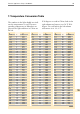
10
Coil Parameters
The ratio between coil and wire diameter
(D/d) must be calculated in order to check
that the coil can easily be made. This ratio
(D/d) should be in the range 5-12 if possi-
ble. In case of supported elements, this ratio
must be compared with the deformation
curve in Figure 3, page 23. When the coil
length and diameter are known, the coil
pitch (s) can be estimated by formula [17] in
the Appendix. Coil pitch (s) is normally 2-4
times the wire diameter (d). For quartz tube
heaters a smaller pitch is normally used.
Preoxidised coils from KANTHAL FeCrAl
in such elements can be used tightly coiled.
For a straight wire on a threaded ceramic
rod and for many elements of the suspended
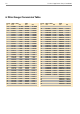
type the wire length is fixed. The resistance
per meter can then be calculated and the
wire size found from the tables of the
Kanthal handbook. If this results in too high
a surface load in case of a ribbon, a wider
and thinner ribbon having the same cross
section can be chosen.
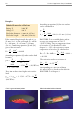
Metal Sheathed Tubular Element
The calculation of a metal sheathed tubular
element is more complicated since the resist-
ance is reduced 10 to 30 % as a result of the
compression of the element. For such ele-
ments, the tube surface load is first deter-
mined according to the use of the element.
The wire surface load is normally 2 to 4
times greater. After calculating the resistance
from rating and voltage, it has to be in-
creased 10 to 30 % in order to arrive at the
resistance after coiling. The wire surface will
become 2 to 7 % smaller when the element
has been reduced. Since the tube length is
increased through compression by rolling,
the tube surface often remains unaltered.
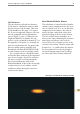
Glowing coil inside tubular heating element.