
Datasheet


68 Kanthal Appliance Alloys Handbook
10. Appendix
1. List of symbols
The symbols used comply as far as
possible with internationally approved
standards.
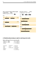
The following symbols are used:
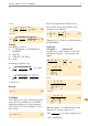
Unit for
Calculation
Symbol Meaning Metric Imperial
A
C
Surface area of heating conductor cm
2
in
2
b Width (ribbon or strip) mm
in
C
t
Temperature factor (ratio of resistivity at operating
temperature to resistivity at room temperature)
d Wire diameter mm
in
D Outer coil diameter mm
in
I Current A
A
L Length of heating conductor m
ft
L
e
Coil length mm
in
p Surface load of heating element W/cm
2
W/in
2
PPower W
W
q Cross-sectional area of heating conductor mm
2
in
2
R
T
Resistance at working temperature ΩΩ
R
20
Resistance at room temperature (20 °C, 68 °F) ΩΩ
s Pitch mm
in
t Thickness (ribbon or strip) mm
in
T. θ Temperature K, °C
K,
°
F
U Voltage V
V
α Temperature coefficient of resistivity K
-1
°
F
-1
γ Density (old marking) g/cm
3
lb/in
3
ρ Resistivity Ω mm
2
m
-1
Ω
/smf*
Ω
/cmf
10 Balancing factor used in the formulas makes possible that the values can be
used with units of section 1:
e.g. wire diameter, d, in [mm] or [in] is different from length of heating
conductor,L in [m] or [ft].
* smf = square mil-foot
cmf = circular mil-foot