KANTHAL HANDBOOK KANTHAL HEATING ALLOYS Handbook KANTHAL AB Box 502, SE-734 27 Hallstahammar, Sweden www.kanthal.
Copyright by Kanthal AB. May be reproduced only with proper acknowledgement of the source. Catalogue 1-A-4-3 Production: ReklamCenter 03057. Printed in Sweden by Primatryck, 2003-02.3000 This information, which may be subject to change, is offered solely for your consideration and should not be taken as warranty or representation for which we assume legal responsibility.
Kanthal Appliance Alloys Handbook Kanthal is never far away! This handbook contains basic technical and product data for our resistance and resistance heating alloys for the appliance industry. We have also included design-, calculation- and application guidelines, in order to make it easier to select the right alloy and to design the right element. More information is given on www.kanthal.com.
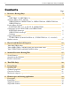
2 Kanthal Appliance Alloys Handbook Contents Page 1. Resistance Heating Alloys NiFe NIFETHAL 70, NIFETHAL 52 Austenitic Alloys (NiCr, NiCrFe) NIKROTHAL 80, NIKROTHAL 70, NIKROTHAL 60, NIKROTHAL 40, NIKROTHAL 20 Ferritic Alloys (FeCrAl) KANTHAL APM, A-1, A, AF, AE, D, ALKROTHAL Comparison between KANTHAL and NIKROTHAL KANTHAL advantages NIKROTHAL advantages Summary Copper Nickel Alloys CUPROTHAL 49, MANGANINA 43, (CUPROTHAL 30, 15, 10 and 05) Product varieties 4 9 11 2.
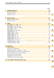
Kanthal Appliance Alloys Handbook 3 Page 7. Standard Tolerances Electrical resistance Diameter of wire Dimensions of cold rolled ribbon 42 42 42 42 8. Delivery forms Resistance heating alloys Resistance alloys 43 43 45 9.
4 Kanthal Appliance Alloys Handbook 1. Resistance Heating Alloys The resistance heating alloys can be divided into two main groups. The FeCrAl (KANTHAL) and the NiCr (NIKROTHAL) based alloys. For lower temperature applications CuNi and NiFe based alloys are also used. The different alloys are described below as well as a comparison of some of the properties of the KANTHAL and the NIKROTHAL alloys.
Kanthal Appliance Alloys Handbook 5 Austenitic Alloys (NiCr, NiCrFe) Ferritic Alloys (FeCrAl) Up to 1200 °C 2190 °F: NIKROTHAL 80 is the austenitic alloy with the highest nickel content. Because of its good workability and high-temperature strength, NIKROTHAL 80 is widely used for demanding applications in the electric appliance industry. Up to 1425 °C 2560 °F: KANTHAL APM (Normally used in furnace applications). Up to 1250 °C 2280 °F: NIKROTHAL 70 (Normally used in furnace applications).
6 Kanthal Appliance Alloys Handbook KANTHAL Advantages Higher maximum temperature in air KANTHAL A-1 has a maximum temperature of 1400 °C 2550 °F; NIKROTHAL 80 has a maximum temperature of 1200 °C 2190 °F. Longer life KANTHAL elements have a life 2-4 times the life of NIKROTHAL when operated in air at the same temperature. Higher surface load Higher maximum temperature and longer life allow a higher surface load to be applied on KANTHAL elements.
Kanthal Appliance Alloys Handbook 7 NIKROTHAL Advantages Better resistance to sulphur In atmospheres contaminated with sulphuric compounds and in the presence of contaminations containing sulphur on the wire surface, KANTHAL alloys have better corrosion resistance in hot state. NiCr alloys are heavily attacked under such conditions.
8 Kanthal Appliance Alloys Handbook KANTHAL Resistance Heating Alloys – Summary °F 2912 °C 1600 2560 °F 1425 °C 1400 2550 °F 1400 °C 2460 °F 1350 °C 2370 °F 1300 °C 2370 °F 1300 °C 2552 2370 °F 1300 °C 2190 °F 1200 °C 1200 2280 °F 1250 °C 2100 °F 1150 °C 2010 °F 1100 °C 2010 °F 1100 °C 2192 1920 °F 1050 °C 1000 1832 800 1472 600 1112 400 752 200 392 -17.8 0 APM A-1 A D KANTHAL AF AE ALKROTHAL 80 70 60 40 NIKROTHAL 20 Fig.
Kanthal Appliance Alloys Handbook 9 Copper-Nickel Alloys CUPROTHAL 49 (universally known as Constantan) is manufactured under close control from electrolytic Copper and pure Nickel. CUPROTHAL 49 has a number of special characteristics – some electrical, some mechanical – which make it a remarkably versatile alloy. For certain applications, its high specific resistance and negligible temperature coefficient of resistance are its most important attributes.
10 Kanthal Appliance Alloys Handbook Copper-Nickel alloys with medium and low resistivity CUPROTHAL 30 KANTHAL produces Copper-Nickel resistivity 30 microhm·cm alloys with resistivities lower than those of CUPROTHAL 15 CUPROTHAL 49 and MANGANINA 43. resistivity 15 microhm·cm The main applications are in high current CUPROTHAL 10 electrical resistances, heating cables, electric resistivity 10 microhm·cm blankets, fuses, resistors but they are also CUPROTHAL 05 used in many other applications.
Kanthal Appliance Alloys Handbook 11 Product Varieties 1 KANTHAL KANTHAL APM Rod Wire Strip Ribbon • • • • • • • • • • • Thin wide Strip Welded tubes Extruded tubes Straightened wire • • • • • • • KANTHAL AE • • • • • • • ALKROTHAL • • • • • • • • • • • • • • • • • • • • KANTHAL A-1 KANTHAL A KANTHAL D, DT • KANTHAL AF • • • NIKROTHAL NIKROTHAL 80 NIKROTHAL 70 NIKROTHAL 60 NIKROTHAL 40 • NIKROTHAL 20 • • KANTHAL/NiFe NIFETHAL 70 • • NIFETHAL 52 • • Copper-Nickel CU
12 Kanthal Appliance Alloys Handbook 2. Physical and Mechanical properties KANTHAL APM A-1 A AF AE 1425 2600 1400 2550 1350 2460 1300 2370 1300 2370 22 5.8 Balance – 22 5.8 Balance – 22 5.3 Balance – 22 5.3 Balance – 22 5.3 Balance – 7.10 0.256 7.10 0.256 7.15 0.258 7.15 0.258 7.15 0.258 Ω mm2m-1 Ω/cmf 1.45 872 1.45 872 1.39 836 1.39 836 1.39 836 Temperature factor of the resistivity, Ct 250 °C 480 °F 930 °F 500 °C 1470 °F 800 °C 1000 °C 1830 °F 1200 °C 2190 °F 1,00 1.01 1.03 1.
Kanthal Appliance Alloys Handbook 13 D NIKROTHAL ALKROTHAL N 80 N 70 N 60 N40 N20 NIFETHAL 70 52 1300 2370 1100 2010 1200 2190 1250 2280 1150 2100 1100 2010 1050 1920 600 1110 600 1110 22 4.8 Balance – 15 4.3 Balance – 20 – – 80 30 – – 70 15 – Balance 60 20 – Balance 35 24 – Balance 20 – – Balance 72 – – Balance 52 7.25 0.262 7.28 0.263 8.30 0.300 8.10 0.293 8.20 0.296 7.90 0.285 7.80 0.281 8.45 0.305 8.20 0.296 1.35 812 1.25 744 1.09 655 1.18 709 1.11 668 1.
14 Kanthal Appliance Alloys Handbook CUPROTHAL 49 MANGANINA 43 CUPROTHAL 30 15 10 05 11 Balance 6 Balance 2 Balance Nominal composition, % Ni Cu Fe Other 44 Balance + 1 Mn 4 Balance 23 Balance 11 Mn 1.5 Mn Density, g/cm3 Ib/in3 8.9 0.321 8.4 0.3+2 8.9 0.321 8.9 0.321 8.9 0.321 8.9 0.321 0.49 295 0.43 259 0.30 180 0.15 90 0.10 60 0.
Kanthal Appliance Alloys Handbook 15 3. Stranded Resistance Heating Wire Recognising the need for more preciesly controlled stranded wire within the cable industry and working closely with our cable customers, Kanthal have developed a range of stranded resistance wires in the well known NIKROTHAL, KANTHAL and Nickel alloys. These alloys possess the optimum properties for high performance at elevated temperatures and in other adverse conditions where reliability and quality is of paramount consideration.
16 Kanthal Appliance Alloys Handbook Standard Stocked Material Strand size mm 19 x 0.544 19 x 0.523 KW 0.574 37 x 0.385 KW 0.45 19 x 0.574 19 x 0.523 KW 0.574 19 x 0.574 19 x 0.574 19 x 0.610 KW 0.71 Alloy Strand diameter nominal, mm NIKROTHAL 80 NIKROTHAL 80 2.67 Strand resistance Ω/m 0.2344-0.2579 0.2886 max. NIKROTHAL 80 2.76 0.276 max. 26 NIKROTHAL 80 NIKROTHAL 60 2.87 0.297 max. 25 30 Nickel Ni Mn2% Ni Mn2% 2.87 0.0243 max. 0.0247 max. 0.0208 max.
Kanthal Appliance Alloys Handbook 17 Flexible Terminations for Industrial Applications Flex Ø, mm CSA, mm2 Strands Weight, gram/m Current, A (low temp. <400 °C) Current, A (high temp. >400 °C) Ω/m, cold Flex Size V. Small 2.3 3.18 7 x 0.76 mm 26.24 7 Small 3.75 8.40 19 x 0.75 mm 70 15 Medium 4.2 10.78 19 x 0.85 mm 86 22 Large 6.7 21.65 49 x 0.75 mm 184 44 X. Large 9.3 38.48 49 x 1.00 mm 325 77 5 15 20 30 45 0.347 0.106 0.102 0.050 0.
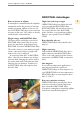
18 Kanthal Appliance Alloys Handbook. 4. Thin Wide Strip Wide and very thin strip has been introduced as an alternative to flattened wire, ribbon, to offer a wider choice of widths than what can be offered via wire flattening. Kanthal has the ability to supply thin wide resistance strip in the thickness range 0,04 to 0,1 mm in widths up to 275 mm produced through rolling and slitting to dimension.
Kanthal Appliance Alloys Handbook. 19 4 Thin strip heating elements for glass top hot plates.
20 Kanthal Appliance Alloys Handbook. 5.
Kanthal Appliance Alloys Handbook. 21 Corrosion Resistance Corrosive or potentially corrosive constituents can considerably shorten wire life. Perspiring hands, mounting or supporting materials or contamination can cause corrosion. Steam Steam shortens the wire life. This effect is more pronounced on NIKROTHAL alloys than on KANTHAL alloys. Halogens Halogens (fluorine, chlorine, bromine and iodine) severely attack all high-temperature alloys at fairly low temperatures.
22 Kanthal Appliance Alloys Handbook. Maximum Temperature per Wire Size The table below gives maximum wire temperatures as a function of wire diameter when operating in air. Table 2 Maximum Permissible Temperature as a Function of Wire Size KANTHAL AF KANTHAL A KANTHAL AE KANTHAL D NIKROTHAL 80 NIKROTHAL 60 NIKROTHAL 40 Diameter, mm (in): 0.15-0.4 (0.0059-0.0157) °C °F 0.41-0.95 (0.0061-0.0374) °C °F 1.0-3.0 (0.039-0.118) °C °F >3.0 (>0.
Kanthal Appliance Alloys Handbook 23 6. Element types and heating applications The Embedded Element Type The Supported Element Type The wire in the embedded element type is completely surrounded by solid or granular insulating material. The wire, normally in spiral form, is situated on the surface, in a groove or a hole of the electrical insulating material. KANTHAL AE, KANTHAL AF and NIKROTHAL 80 are generally the best materials.
24 Kanthal Appliance Alloys Handbook Embedded Elements Metal Sheathed Tubular Elements Characteristics The heating coil is insulated from the encasing metallic tube by granular material (MgO). The tube is compressed to a round, oval or triangular shape. Terminals may be at either end or at one end of the element (cartridge type). Recommended alloy KANTHAL D in elements with sheath temperature <700°C <1290°F. NIKROTHAL 80 in elements with sheath temperature >700°C >1290°F.
Kanthal Appliance Alloys Handbook 25 Embedded Elements Elements Embedded in Ceramics Characteristics Heating coil is embedded in green ceramics (subsequently fired), or cemented in grooves in ceramic bodies. Recommended alloy KANTHAL A for high temperature firing. KANTHAL D for other applications. Surface load Wire: 5-10 W/cm2 30-60 W/in2 Typical applications Panel heaters, IR heaters, warming plates, irons, ceramic pots.
26 Kanthal Appliance Alloys Handbook Embedded Elements Coils in grooved Metal Plates Characteristics Heating coil and insulating powder are pressed into grooves of a metal plate. Recommended alloy KANTHAL D Surface load Wire: 4-20 W/cm2 25-130 W/in2 Typical applications Cast iron plates; also, irons, warming plates, kettles, domestic ovens.
Kanthal Appliance Alloys Handbook 27 Embedded Elements Cartridge Elements, Powder filled Characteristics Straight wire or coil is wound on a threaded ceramic body and insulated by granular insulating material (MgO) from enveloping metal tube. Terminals are at one end of the element. Elements are compressed when high-loaded. Recommended alloy NIKROTHAL 80 in straight wire elements. KANTHAL D in coiled wire elements. Surface load On tube: 10-25 W/cm2 65-160W/in2 for elements with straight wire.
28 Kanthal Appliance Alloys Handbook Embedded Elements Heating Cables and Rope Heaters Characteristics Wire is wound on a fibreglass core and insulated by PVC or silicone rubber (higher temperatures). Fiberglass insulation permits even higher temperatures. Heating cables with straight or stranded wires, sometimes enclosed in aluminium tube, also occur.
Kanthal Appliance Alloys Handbook 29 Embedded Elements Mica Elements Characteristics Resistance ribbon or wire is wound on mica sheet or tube and insulated by mica. Elements are often encapsulated in steel sheaths. Recommended alloy KANTHAL D NIKROTHAL 80 Surface load Wire: 2-10 W/cm2 13-65 W/in2 Typical applications Irons, ironing machines, water heaters, plastic moulding dies, soldering irons.
30 Kanthal Appliance Alloys Handbook Supported Elements Ceramic Cartridge Elements Characteristics Most common design consists of round ceramic bodies with longitudinal holes or grooves for heating coil. Elements are often in metallic tube with terminals at one end. Often provisions are made to avoid excessive sagging of the coil when the element is operating vertically. Recommended alloy KANTHAL A or D for horizontally operating coils.
Kanthal Appliance Alloys Handbook 31 Supported Elements Other ceramic elements Characteristics Coiled and straight wire is located on smooth ceramic tube or in grooves or holes of ceramic bodies of various shapes (plates, tubes, rods, cylinders, etc.). Recommended alloy KANTHAL A, AF and D. NIKROTHAL 80 (for pencil bars). Surface load Wire: 3-9 W/cm2 20-60 W/in2 Typical applications Boiling plates, air guns, hobby kilns, radiators.
32 Kanthal Appliance Alloys Handbook Supported Elements Quartz Tube Heaters Characteristics Heating coil is placed inside quartz tube (or tube of glass ceramic). When the element is operating vertically or at an angle, the coil should be tight-wound and pre-oxidized. For horizontal use, the relative pitch is 1.2-2.0. Recommended alloy KANTHAL AE, AF, A and D.
Kanthal Appliance Alloys Handbook 33 Supported Elements Elements on moulded ceramic fibre Characteristics Heating coil rests on moulded ceramic fibre plate, with or without grooves. Coils are cemented or stapled at intervals, or pressed into ribs on this surface. Thin wide strip, normally in corrugated shape, is more and more common as an alternative to coiled wire. Ribbon has also been used. Recommended alloy KANTHAL AE or AF.
34 Kanthal Appliance Alloys Handbook Supported Elements Bead insulated coils or stranded wire Characteristics Heating coil, or stranded wire, is insulated by ceramic beads. With beads having two holes heating mats are made. Recommended alloy KANTHAL D, NIKROTHAL 80 (for panel heaters). Surface load Wire: 1-8 W/cm2 6.5-52 W/in2 Typical applications Mats for in-situ annealing of welded parts, panel heaters, waffle irons, domestic ovens, water heater.
Kanthal Appliance Alloys Handbook 35 Supported Elements String Elements Characteristics Heating wire wound on insulated steel wire (approx. 2 mm 0.008 in) or fibre glass cord. Recommended alloy KANTHAL D. Surface load Wire: <10 W/cm2 <65 W/in2 Typical applications Stationary hair dryers.
36 Kanthal Appliance Alloys Handbook Suspended Elements Suspended coils Characteristics Wire coil is supported at intervals, e.g. by ceramic holders. Fibreglass cord is often placed inside coil to prevent the coil from falling down in case of element failure. Recommended alloy NIKROTHAL 80 and NIKROTHAL 60 KANTHAL D and AF (mainly for wire temperatures below 600°C 1110°F, where sagging is no problem). Surface load Wire: 7-8 W/cm2 45-50 W/in2 in forced air; 3-4 W/cm2 20-25 W/in2 in natural convection.
Kanthal Appliance Alloys Handbook 37 Suspended Elements Suspended straight wires and ribbons Characteristics Wire or ribbon may have elastic or fixed suspension. Elastic: Wire kept straight by springs when heated. Fixed: Operating temperature is lower and low thermal expansion is advantageous. Recommended alloy KANTHAL A and AF (low thermal expansion) NIKROTHAL 80 Surface load Wire: 4-12 W/cm2 25-77 W/in2 Typical applications Radiators, toasters, convection heaters, hair dryers.
38 Kanthal Appliance Alloys Handbook Suspended Elements Open Mica Elements Characteristics Straight or corrugated heating wire is wound on one or both sides of a mica sheet or separated mica strips. Ribbons are frequently used in this application. Recommended alloy NIKROTHAL 80, NIKROTHAL 60, KANTHAL D and AF. Surface load Wire: 4-7 W/cm2 25-45 W/in2 For toasters: < 13 W/cm2 <26-52 W/in2 for wire-wound elements Typical applications Toasters; also, convection heating, low-watt aquarium heaters.
Kanthal Appliance Alloys Handbook 39 Suspended Elements Zig-zag Elements Characteristics Deep-corrugated ribbon is supported by mica sheets. Also radial shape. Recommended alloy KANTHAL D, AF and NIKROTHAL 40 Surface load Wire: 9 W/cm2 60 W/in2 Typical applications Fan heaters, convection heating.
40 Kanthal Appliance Alloys Handbook Suspended Elements Porcupine Elements Characteristics Heating conductor consists of hairpin- shaped wire bends protruding in all directions, with hole in centre. Element is supported by central insulated rod or insulating tube around its circumference. Recommended alloy KANTHAL D, AF NIKROTHAL 80 Surface load Wire: 4W/cm2 25 W/in2 in natural convection, <12 W/cm2 75 W/in2 in forced convection.
Kanthal Appliance Alloys Handbook 41 Suspended Elements Coils immersed in water Characteristics Wire coils operating directly in water. Recommended alloy KANTHAL D and AF NIKROTHAL 80. Surface load Wire: Depending on water velocity, 20-60 W/cm2 130-390 W/in2 (even higher figures occur.) Typical applications Instantaneous tap water and shower heaters, steam generators.
42 Kanthal Appliance Alloys Handbook. 7. Standard Tolerances Standard tolerances for wire and ribbon are given below. Size tolerances do not apply to material manufactured to resistance tolerances and vice-versa. Tolerances on electrical resistance Resistance of wire at 20 °C Diameter ≤ 0.127 mm 0.0048 in ±8 %. All dimensions >0.127 mm 0.0048 in ±5 %. Resistance of ribbon For cold rolled strips and ribbon, all widths and thickness’ ± 5%.
Kanthal Appliance Alloys Handbook. 43 8. Delivery Forms In order to avoid transport damage all goods are carefully packed in card board boxes or wooden cases, with suitable internal protection. Resistance Heating alloys (KANTHAL, ALKROTHAL, NIKROTHAL, NIFETHAL 70 and 52) Wire Wire of ≤1.63 mm is delivered on spools, such as shown in the figure. Only one length of wire is wound on each spool. Wire sizes between 0.40 and 1.
44 Kanthal Appliance Alloys Handbook. Thin wide strip Standard delivery is in coil form on inner core. For full width material the core is a recyclable steel tube with inner diameter 400 mm. For narrow slit widths the core is made of hard paper or plastic with inner diameter 200-400 mm depending on strip width and request. On special demand, narrow slit strip up to 10 mm can be delivered pitch wound on a special spool. Coil weight or strip lengths are subject to special agreements.
Kanthal Appliance Alloys Handbook. 45 Resistance alloys (CUPROTHAL 49, 30, 15, 10, 5 and MANGANINA 43) The wire is normally packed as shown below. Wire and ribbon can also be specially packed to individual requirements. To provide additional protection to the materials, spools are wrapped with plastic film or closed in plastic boxes. Wire Wire up to 1.40 mm is available on spools. At the request of the customer, wire can also be supplied in annular drums as detailed below.
46 Kanthal Appliance Alloys Handbook Types of Ribbon Spools Spool No. Tare g Spool measurements, mm D d l d1 L Capacity, kg KANTHAL NIKROTHAL K 80 K 100 K 125 K 200 70 125 200 600 80 100 125 200 16 16 16 36 80 100 125 200 0.7 1.5 3 10 0.8 1.9 3.5 11 50 63 80 125 64 80 100 160 Rods Available shaved or not shaved depending on the alloy. In order to avoid transport damage all goods are carefully packed in cardboard boxes or wooden cases, with suitable internal protection.
Kanthal Appliance Alloys Handbook. 47 9. Tables The tables show metric values for wire and ribbon. There are other editions of this handbook for Imperial values (SWG and B&S). For dimensions in the range 0.12-0.010 mm 0.0047-0.0004 in, we recommend the Kanthal Precision Technology Handbook. The larger dimensions and different elements are described more in detail in the Kanthal Handbook Resistance Heating Alloys and Systems for Industrial Furnaces.
48 Kanthal Appliance Alloys Handbook KANTHAL A-1, APM Wire Standard stock items Alloy Diameter range mm Resistivity Ωmm2m-1 Density gcm-3 ■ ■ KANTHAL A-1 KANTHAL APM 10.0-0.050 10.0-0.20 1.45 1.45 7.10 7.10 To obtain resistance at working temperature, multiply by the factor Ct in the following table: °C Ct 20 1.00 Diameter mm A-1 APM 10.0 9.5 8.25 8.0 7.35 7.0 6.54 6.5 6.0 5.83 5.5 5.0 4.75 4.62 4.5 4.25 4.11 4.06 4.0 3.75 3.65 3.5 3.35 3.25 3.2 1) 10.0 9.5 9.27 8.25 8.0 7.35 7.0 6.5 6.
Kanthal Appliance Alloys Handbook. 49 KANTHAL A, AF, AE Wire Standard stock items Alloy Diameter range mm Resistivity Ωmm2m-1 Density gcm-3 ■ ■ – KANTHAL A KANTHAL AF KANTHAL AE 10.0-0.05 10.0-0.10 10.0-0.20 1.39 1.39 1.39 7.15 7.15 7.15 To obtain resistance at working temperature, multiply by the factor Ct in the following table: °C Ct 20 1.00 Diameter mm A AF 10 1) 10.0 8.25 8.0 7.5 7.35 7.0 6.54 6.5 6.0 5.83 5.5 5.2 5.0 4.75 4.62 4.5 4.25 4.11 4.0 3.75 3.65 3.5 3.25 3.2 3.0 2.9 2.8 2.
50 Kanthal Appliance Alloys Handbook KANTHAL A, AF, AE Ribbon Alloy Resistivity Ωmm2m-1 Density gcm-3 KANTHAL A, AF, AE 1.39 7.15 To obtain resistance at working temperature, multiply by the factor Ct in the following table: °C Ct 20 1.00 100 1.00 ResisThick- tance Width ness at 20 °C mm mm Ω/m 4 3 2.5 2.0 1) 1.0 0.90 0.80 0.70 0.60 0.50 0.40 0.30 0.20 0.15 0.10 1.0 0.90 0.80 0.70 0.60 0.50 0.40 0.30 0.20 0.15 0.10 1.0 0.90 0.80 0.70 0.60 0.50 0.40 0.30 0.20 0.15 0.10 1.0 0.90 0.80 0.70 0.
Kanthal Appliance Alloys Handbook. 51 (cont.) KANTHAL A, AF, AE Ribbon Alloy Resistivity Ωmm2m-1 Density gcm-3 KANTHAL A, AF, AE 1.39 7.15 To obtain resistance at working temperature, multiply by the factor Ct in the following table: °C Ct 20 1.00 100 1.00 ResisThick- tance Width ness at 20 °C mm mm Ω/m 1.0 0.9 0.8 0.7 1) 0.20 0.15 0.10 0.090 0.080 0.070 0.060 0.050 0.70 0.60 0.50 0.40 0.30 0.20 0.15 0.10 0.090 0.080 0.070 0.060 0.050 0.70 0.60 0.50 0.40 0.30 0.20 0.15 0.10 0.090 0.080 0.
52 Kanthal Appliance Alloys Handbook KANTHAL D Wire Standard stock items Alloy Diameter range mm Resistivity Ωmm2m-1 Density gcm-3 ■ D 8.0-0.020 1.35 7.25 To obtain resistance at working temperature, multiply by the factor Ct in the following table: °C Ct 20 1.00 Diameter mm Resistance at 20 °C cm2/Ω1) Ω/m at 20 °C Weight g/m Surface area cm2/m Cross sectional area mm2 Diameter mm Resistance at 20 °C cm2/Ω1) Ω/m at 20 °C Weight g/m Cross Surface sectional area area cm2/m mm2 8.0 6.
Kanthal Appliance Alloys Handbook. 53 KANTHAL D, DT Ribbon Alloy Resistivity Ωmm2m-1 Density gcm-3 KANTHAL D KANTAHL DT 1.39 1.37 7.25 7.25 To obtain resistance at working temperature, multiply by the factor Ct in the following table: °C Ct 20 1.00 100 1.00 ResisThick- tance Width ness at 20 °C mm mm Ω/m 4 3 2.5 2.25 1) 1.0 0.90 0.80 0.70 0.60 0.50 0.40 0.30 0.20 0.15 0.10 1.0 0.90 0.80 0.70 0.60 0.50 0.40 0.30 0.20 0.15 0.10 1.0 0.90 0.80 0.70 0.60 0.50 0.40 0.30 0.20 0.15 0.10 1.0 0.
54 Kanthal Appliance Alloys Handbook (cont.) KANTHAL D, DT Ribbon Alloy Resistivity Ωmm2m-1 Density gcm-3 KANTHAL D KANTAHL DT 1.39 1.37 7.25 7.25 To obtain resistance at working temperature, multiply by the factor Ct in the following table: °C Ct 20 1.00 100 1.00 ResisThick- tance Width ness at 20 °C mm mm Ω/m 1.25 1.0 0.9 0.8 0.7 1) 0.080 0.070 0.60 0.50 0.40 0.30 0.20 0.15 0.10 0.090 0.080 0.070 0.060 0.050 0.50 0.40 0.30 0.20 0.15 0.10 0.090 0.080 0.070 0.060 0.050 0.50 0.40 0.30 0.
Kanthal Appliance Alloys Handbook. 55 ALKROTHAL Wire Alloy Diameter range mm Resistivity Ωmm2m-1 Density gcm-3 ALKROTHAL 6.5-0.10 1.25 7.28 To obtain resistance at working temperature, multiply by the factor Ct in the following table: °C Ct 20 1.00 Diameter mm Resistance at 20 °C cm2/Ω1) Ω/m at 20 °C Weight g/m Surface area cm2/m Cross sectional area mm2 Diameter mm Resistance at 20 °C cm2/Ω1) Ω/m at 20 °C Weight g/m Surface area cm2/m Cross sectional area mm2 6.5 6.0 5.5 5.0 4.75 4.
56 Kanthal Appliance Alloys Handbook ALKROTHAL Ribbon Alloy Resistivity Ωmm2m-1 Density gcm-3 ALKROTHAL 1.25 7.28 To obtain resistance at working temperature, multiply by the factor Ct in the following table: °C Ct 20 1.00 100 1.00 ResisThick- tance Width ness at 20 °C mm mm Ω/m 4 3 2.5 2.25 1) 1.0 0.90 0.80 0.70 0.60 0.50 0.40 0.30 0.20 0.15 0.10 1.0 0.90 0.80 0.70 0.60 0.50 0.40 0.30 0.20 0.15 0.10 1.0 0.90 0.80 0.70 0.60 0.50 0.40 0.30 0.20 0.15 0.10 1.0 0.90 0.80 0.70 0.60 0.50 0.40 0.
Kanthal Appliance Alloys Handbook. 57 (cont.) ALKROTHAL Ribbon Alloy Resistivity Ωmm2m-1 Density gcm-3 ALKROTHAL 1.25 7.28 To obtain resistance at working temperature, multiply by the factor Ct in the following table: at working the factor the following table: °C 20To obtain 100 resistance 200 300 400 temperature, 500 600 multiply 700 by800 900 Ct in 1000 1100 Ct 1.00 1.00 ResisThick- tance Width ness at 20 °C mm mm Ω/m 1.25 1.0 0.9 0.8 0.7 1) 0.080 0.070 0.60 0.50 0.40 0.30 0.20 0.15 0.
58 Kanthal Appliance Alloys Handbook NIKROTHAL 80, 70 Wire Standard stock items Alloy Diameter range mm Resistivity Ωmm2m-1 Density gcm-3 ■ – NIKROTHAL 80 NIKROTHAL 70 8.0-0.020 10.0-0.50 1.09 1.18 8.30 8.10 To obtain resistance at working temperature, multiply by the factor Ct in the following table: °C 20 N 80 Ct 1.00 N 70 Ct 1.00 100 1.01 1.01 200 1.02 1.02 300 1.03 1.03 400 1.04 1.04 500 1.05 1.05 600 1.04 1.05 700 1.04 1.04 800 1.04 1.04 900 1.04 1.04 1000 1.05 1.05 1100 1.06 1.
Kanthal Appliance Alloys Handbook. 59 NIKROTHAL 60 Wire Alloy Diameter range mm Resistivity Ωmm2m-1 Density gcm-3 NIKROTHAL 60 6.0-0.015 1.11 8.20 To obtain resistance at working temperature, multiply by the factor Ct in the following table: °C Ct 20 1.00 Diameter mm Resistance at 20 °C cm2/Ω1) Ω/m at 20 °C Weight g/m Surface area cm2/m Cross sectional area mm2 6.0 5.5 5.0 4.75 4.5 4.25 4.0 3.75 3.5 3.25 3.0 2.8 2.6 2.5 2.2 2.0 1.9 1.8 1.7 1.6 1.5 1.4 1.3 1.2 1.1 1.0 0.95 0.90 0.85 0.
60 Kanthal Appliance Alloys Handbook NIKROTHAL 40, 20 Wire Alloy Diameter range mm Resistivity Ωmm2m-1 Density gcm-3 NIKROTHAL 40 NIKROTHAL 20 6.0-0.10 6.0-0.10 1.04 0.95 7.90 7.80 To obtain resistance at working temperature, multiply by the factor Ct in the following table: °C 20 N40 Ct 1.00 N20 Ct 1.00 100 1.03 1.04 200 1.06 1.10 300 1.10 1.14 400 1.12 1.17 500 1.15 1.21 600 1.17 1.12 700 1.19 1.16 800 1.21 1.28 900 1.22 1.30 1000 1.23 1.32 1100 1.24 1.
Kanthal Appliance Alloys Handbook. 61 NIKROTHAL 80, 60, 40 Ribbon Alloy Resistivity Ωmm2m-1 Density gcm-3 NIKROTHAL 80 NIKROTHAL 60 NIKROTHAL 40 1.09 1.11 1.04 8.30 8.20 7.90 To obtain resistance at working temperature, multiply by the factor Ct in the following table: °C N80 Ct N60 Ct N40 Ct 20 1.00 1.00 1.00 100 1.01 1.02 1.03 200 1.02 1.04 1.06 300 1.03 1.05 1.10 400 1.04 1.06 1.12 500 1.05 1.08 1.15 600 1.04 1.09 1.17 700 1.04 1.09 1.19 800 1.04 1.10 1.21 900 1.04 1.10 1.22 1000 1.
62 Kanthal Appliance Alloys Handbook (cont.) NIKROTHAL 80, 60, 40 Ribbon ResisThick- tance Width ness at 20 °C mm mm Ω/m 1.0 0.9 0.8 0.7 1) 0.40 0.30 0.20 0.15 0.10 0.090 0.080 0.070 0.80 0.70 0.60 0.50 0.40 0.30 0.20 0.15 0.10 0.090 0.080 0.070 0.060 0.050 0.70 0.60 0.50 0.40 0.30 0.20 0.15 0.10 0.090 0.080 0.070 0.060 0.050 0.70 0.60 0.50 0.40 0.30 0.20 0.15 0.10 0.090 0.080 0.070 0.060 0.050 0.60 0.50 2.47 3.29 4.94 6.58 9.87 11.0 12.3 14.1 1.48 1.69 1.97 2.37 2.96 3.95 5.92 7.90 11.8 13.2 14.
Kanthal Appliance Alloys Handbook. 63 NIFETHAL 70 and 52 Wire Alloy Diameter range mm Resistivity Ωmm2m-1 Density gcm-3 NIFETHAL 70 NIFETHAL 52 4.0-0.10 4.0-0.10 0.20 0.43 8.45 8.20 To obtain resistance at working temperature, multiply by the factor Ct in the following table: °C NIFETHAL 70 Ct NIFETHAL 52 Ct 20 1.00 1.00 100 1.42 1.33 150 1.68 1.53 200 1.91 1.73 250 2.19 1.93 300 2.47 2.13 350 2.75 2.32 400 3.03 2.49 450 3.34 2.64 500 3.66 2.
64 Kanthal Appliance Alloys Handbook Copper-Nickel Wire Alloy Diameter range mm Resistivity Ωmm2m-1 Density gcm-3 CUPROTHAL 49 MANGANINA 43 CUPROTHAL 30 CUPROTHAL 15 CUPROTHAL 10 CUPROTHAL 05 4.0-0.10 8.0-0.10 4.0-0.10 4.0-0.10 4.0-0.10 4.0-0.10 0.49 0.43 0.30 0.15 0.10 0.05 8.90 8.40 8.90 8.90 8.90 8.90 To obtain resistance at working temperature, multiply by the factor Ct in the following table: 20 °C 1.000 1.000 1.000 1.000 1.
Kanthal Appliance Alloys Handbook. 65 (cont.) Copper-Nickel Wire Alloy Diameter range mm Resistivity Ωmm2m-1 Density gcm-3 CUPROTHAL 49 MANGANINA 43 CUPROTHAL 30 CUPROTHAL 15 CUPROTHAL 10 CUPROTHAL 05 4,0-0.10 8.0-0.10 4.0-0.10 4.0-0.10 4.0-0.10 4.0-0.10 0.49 0.43 0.30 0.15 0.10 0.05 8.90 8.40 8.90 8.90 8.90 8.90 To obtain resistance at working temperature, multiply by the factor Ct in the following table: 20 °C 1.000 1.000 1.000 1.000 1.
66 Kanthal Appliance Alloys Handbook Copper-Nickel Ribbon Alloy Resistivity Ωmm2m-1 Density gcm-3 CUPROTHAL 49 0.49 8.90 To obtain resistance at working temperature, multiply by the factor Ct in the following table: Alloy CUPROTHAL 49 ResisThick- tance Width ness at 20 °C mm mm Ω/m 4 3 2.5 2.0 1) 1.0 0.90 0.80 0.70 0.60 0.50 0.40 0.30 0.20 0.15 0.10 1.0 0.90 0.80 0.70 0.60 0.50 0.40 0.30 0.20 0.15 0.10 1.0 0.90 0.80 0.70 0.60 0.50 0.40 0.30 0.20 0.15 0.10 1.0 0.90 0.80 0.70 0.60 0.50 0.40 0.
Kanthal Appliance Alloys Handbook. 67 (cont.) Copper-Nickel Ribbon Alloy Resistivity Ωmm2m-1 Density gcm-3 CUPROTHAL 49 0.49 8.90 To obtain resistance at working temperature, multiply by the factor Ct in the following table: Alloy CUPROTHAL 49 ResisThick- tance Width ness at 20 °C mm mm Ω/m 1.0 0.9 0.8 0.7 1) 0.10 0.090 0.080 0.070 0.060 0.050 0.70 0.60 0.50 0.40 0.30 0.20 0.15 0.10 0.090 0.080 0.070 0.060 0.050 0.70 0.60 0.50 0.40 0.30 0.20 0.15 0.10 0.090 0.080 0.070 0.060 0.050 0.60 0.
68 Kanthal Appliance Alloys Handbook 10. Appendix 1. List of symbols The symbols used comply as far as possible with internationally approved standards.
Kanthal Appliance Alloys Handbook 69 2. Formulas and Definitions The following formulas and definitions are applied to all applications. Definition : Resistivity R [Ωmm2/m] or [Ω/cmf ] The resistance of a conductor, R20, is directly proportional to its length, L and inversely proportional to its cross-sectional area, q: R20 = ρ L q [1] [Ω] The proportional constant, ρ is defined as the resistivity of the material and is temperature dependent.
70 Kanthal Appliance Alloys Handbook General formulas Definition: Cross sectional area q U = RT · I [V] [9] A) Round wire q= [W] P=U·I [10] [mm2] or [in2] π · d2 [mm2] or [in2] 4 [12] Combining equations [1], [6], [7] and [12] gives the wire diameter, d: Combining equations [9] and [10] gives: U2 R Rating I 2. U R R U.I P.R P I Voltage P I U R I.
Kanthal Appliance Alloys Handbook 71 metric L ρ·P 4 [mm] · · π2 p · R20 10 d= 3 [13] ρ·P L 4 · [in] [13] · 2 p · R 15.28 · 106 π 20 Example: According to section 2 ρ = 1.35 Ω mm2/m = (812 Ω/cmf ) for Kanthal D P = 1000 W p = 8 W/cm2 (51.6 W/in2) R = 40 Ω d= 3 π · (D – d) 2 L +1= Le s s= L 4 812 ·1000 · · = 15.28 · 106 π2 51.6 · 40 metric = 0.
72 s= Kanthal Appliance Alloys Handbook π · (D – d) · Le L [17] Relative pitch s/d The ratio s/d is often used. It is called the relative pitch or the stretch factor, and may affect the heat dissipation from the coil. s [--] r= d The ratio D/d is essential for the coiling operation, as well as the mechanical stability of the coil in a hot state. Example – wire calculation: Calculate the resistance of a 3-foot-long KANTHAL D wire, 22 B & S (0.02535 in diameter).
Kanthal Appliance Alloys Handbook 73 3. Formulas for Values in Chapter 9, Tables In the Kanthal handbook values per meter of the material in each dimension are calculated and presented in the table as surface area, weight, resistance. Furthermore are the cross sectional area and area /Ω calculated. Below you can see formulas used (formulas include the unit correction) Metric units: Cross sectional area q [mm2] Based on equation [12] [14] res.
74 Kanthal Appliance Alloys Handbook Surface area per Ω [cm2/ Ω] Combining [1’] and [7’] respectively [1’] and [8’] Wire AC/m π · d · q · 10 π2 · d3 · 10 = = ρ ρ·4 R20/m Strip AC/m R20/m = R20/m = = R20/m · 1000 ρ · 1000 ρ · 1000 = = q·q·γ q2 · γ mm Wire 2 · (b + t) · b · t ·10 = ρ Strip = Rkg = Rkg = Other equations which could be helpful Length per kilo, Lkg [m/kg] 1000 Based on equation [18] ➔ Lkg = mm Wire 4000 Lkg = 1000 · 4 = [18’] 2 π·d ·γ π · d2 · γ Strip Lkg = 1000 b·t·γ [18’] Ribbon 1
Kanthal Appliance Alloys Handbook 75 Ribbon Imperial units ρ′wire’ = Ω /cir.mil foot respectively ρ′strip/ribbon= Ω /square mil foot. mft = 0.92 · b · t · γ · 12 = 11.04 · b · t · γ [18’] Cross sectional area q [in2] Based on equation [12] [14] res. [15] Resistance per foot R20 / ft Wire Based on equation [1] ➔ R20 / ft = q= π · d2 4 [12’] q= b · t [14’] q = 0.92 · b · t [15’] Surface area per foot AC / ft [in /ft] Based on equation [7] res.
76 Kanthal Appliance Alloys Handbook Other equations which could be helpful Length per lb llb [ft/lb] 1 Based on equation [18] ➔ llb = mft Wire 4 1 llb = = [18’] 2· γ · 3 2 π · d π · d · γ ·12 Strip llb = 1 b · t · γ · 12 [18’] 1 1 = 0.92 · b · t · γ · 12 b · t · γ · 11.
Kanthal Appliance Alloys Handbook 77 5. Design Calculations for Heating Elements In this section an element is defined as the combination of heating wire and any supporting and connecting materials. Electrical appliances equipped with a heating element are being used in domestic as well as industrial applications. Domestic applications are e.g. cooking, heating of fluids, drying, ironing, space heating and special purposes such as heating of beds, aquariums, saunas, soldering irons and paint strippers.
78 Surface Load When calculating an element, voltage and rating are normally known. The element surface load means the rating divided by that part of element surface, which is close to the energised wire and therefore has an elevated temperature. Usually a range of surface loads and not one single figure is listed in the mentioned tables. The choice within the range depends upon the requirements for the element. It also depends upon voltage, rating and dimensions available.
Kanthal Appliance Alloys Handbook Coil Parameters The ratio between coil and wire diameter (D/d) must be calculated in order to check that the coil can easily be made. This ratio (D/d) should be in the range 5-12 if possible. In case of supported elements, this ratio must be compared with the deformation curve in Figure 3, page 23. When the coil length and diameter are known, the coil pitch (s) can be estimated by formula [17] in the Appendix. Coil pitch (s) is normally 2-4 times the wire diameter (d).
80 Kanthal Appliance Alloys Handbook Examples Tubular Element for a Flat Iron Rating, P Voltage. U Final tube diameter: Final tube length: 1000 W 220 V 8 mm (0.315 in) 300 mm (11.8 in) If the terminal length inside the tube is 2 x 25 mm (2 x 1 in) the coil length (Le) will be Le = 300 mm – (2 x 25 mm) = 250 mm (9.8 in). Combining equation [9] and [10] gives as hot resistance U2 2202 48.4 Ω = = R= P 1000 According to equation [6] tubes surface load becomes P = P = ptube = Atube π · dtube · Le · 0.
Kanthal Appliance Alloys Handbook We assume that a steel tube of initially 9.5 mm (0.37 in) diameter is being used and can then expect a resistance reduction of about 30 % upon rolling. The resistance of the coil should therefore be about 65.3 Ω. The wire surface prior to compression is 7 % bigger, or 22.5 cm2 (3.49 in2), and the ratio between wire surface and resistance 0.34 cm2/Ω (0.053 in2/Ω). The corresponding wire size is 0.26 mm (0.01 in).
82 Kanthal Appliance Alloys Handbook 6. Wire Gauge Conversion Table Gauge no. AWG or B&S inch mm SWG inch mm Gauge no. AWG or B&S inch mm SWG inch mm 4-0 3-0 2-0 0 1 2 3 4 5 6 7 8 9 10 11 12 13 14 15 16 17 18 19 20 21 22 23 24 25 26 27 28 0.4600 0.4096 0.3648 0.3249 0.2893 0.2576 0.2294 0.2043 0.1819 0.1620 0.1443 0.1285 0.1144 0.1019 0.09074 0.08081 0.07196 0.06408 0.05707 0.05082 0.04526 0.04030 0.03589 0.03196 0.02846 0.02535 0.02257 0.02010 0.01790 0.01594 0.01420 0.01264 0.4000 0.3720 0.
Kanthal Appliance Alloys Handbook 83 7. Temperature Conversion Table If 10 degrees are read in Celsius, look in the right column and convert it to 50 °F. If 10 degrees F is read, look in the left column and convert it to -12,2 °C. The numbers in the light shaded area indicate the temperatures as read. The corresponding temperatures in Fahrenheit are given on the right and those in Celsius on the left. °C –17.8 –17.2 –16.7 –16.1 –15.6 –15.0 –14.4 –13.9 –13.3 –12.8 –12.2 –11.7 –11.1 –10.6 –10.0 –9.44 –8.
84 Kanthal Appliance Alloys Handbook cont.
Kanthal Appliance Alloys Handbook 85 cont.
86 Kanthal Appliance Alloys Handbook 8.
Kanthal Appliance Alloys Handbook To Convert from: foot-pounds/sec furlongs gallons (U.S.
88 To Convert from: kilogram-calories kg-cals/minute kilogram-meters kgs/cu meter kgs/cu meter kgs/cu meter kgs/meter kgs/sq centimeter kgs/sq meter kgs/sq meter kilopascals kilowatt kilowatt-hours kilowatt-hours kilowatt-hours kilowatt-hours liter liter liters liters/minute liters/minute meters meters meters meter-kilograms meters/second meters/second meters/second meters/second micrograms microhms microinches microinches microinches microliters microns microns microns miles millibars millibars millihenri
Kanthal Appliance Alloys Handbook To Convert from: oersteds ohm - circular mil/foot ohm - circular mil/foot ohm - circular mil/foot ohms/foot ounces ounces (fluid) ounces (fluid) ounces (troy) ounces (troy) pound pound pound pounds (troy) pounds/sq foot pounds/sq inch pounds/cubic foot pounds/cubic inch radians radians/sec slugs square centimeters square feet square millimeters square mils square mils square mils stones watts watts watts watts watt-hours watt-hours To: amperes/meter ohm - square mil/foot
90 Kanthal Appliance Alloys Handbook 11. The Kanthal Product Range Heating Alloys Precision Wire Appliance Wire 0.12-2 mm 0.00468-0.078 in Ribbon The heating source in most electric household appliances such as ovens, toasters, hair dryers, washing machines etc. Precision Wire 0.015-0.12 mm 0.000585-0.00468 in Is used in electronic components such as resistors and potentiometers and for low temperature heating. Industrial Wire 1-10 mm 0.039-0.
Kanthal Appliance Alloys Handbook 91 Thermostatic Bimetal Kanthal Super Bimetal consists of two or more metallic strips with different thermal expansion bonded together. When heated up it bends in a pre-determined manner and can be used to monitor, measure or regulate heat. Its main applications are in thermostats for room heaters or water mixing but they are also used to control toasters and indicators in automobiles.
92 Kanthal Appliance Alloys Handbook Metallic Elements FIBROTHAL® Ready-made furnace elements manufactured in Kanthal workshops from KANTHAL or NIKROTHAL alloys for furnace temperatures between 50 °C – 1350 °C 120 – 2460 °F. A complete modular system comprising heating elements and insulation for furnaces and processes up to 1200 °C 2190 °F. FIBROTHAL. Metallic elements manufacturing.
Kanthal Appliance Alloys Handbook 93 TUBOTHAL® Tubes Powerful metallic element heaters for use inside all types of radiant tubes, ideally KANTHAL APM. Available in standard dimensions from 68 to 170 mm diameter 2.6 - 6.6 in. KANTHAL APM and SANDVIK 253/353 MA extruded radiant tubes for gas- or electrically heated furnaces. Complete assemblies with inner tubes (gas) or suitable electric heating elements. Standard dimensions from 26 to 260 mm outer diameter 1.02- 10.2 in.
94 Kanthal Appliance Alloys Handbook Heating Elements Silicon Carbide Furnace systems and complete heating elements for semiconductor wafer processing. Furnace rebuilds, upgrades and new replacement rnace systems to provide larger wafer processing capabilities. Heating elements in a broad range for use up to 1650 °C 3000 °F. Manufactured in straight, spiralled, single or multi-shank designs for a variety of heat treatment and melting furnaces.
Kanthal Appliance Alloys Handbook 95 Kanthal Machinery Customer Service Kanthal Machinery offers a complete range of machines for manufacturing of tubes and metal sheathed tubular elements. Available as either standard or custom built stand-alone machines to complete turnkey factory production lines. Kanthal not only offers a complete range of products to generate or protect against heat, but of equal importance is the technical and commercial service we extend to our customers.
96 Kanthal Appliance Alloys Handbook Visit www.kanthal.com You will always find the latest information about Kanthal and our products on the web. Brochures, handbooks and data-sheets can be downloaded to your computer. You will find address, e-mail, fax- and telephone numbers to all Kanthal subsidiaries and representatives, press releases and other news. Kanthal is a Sandvik Company.
KANTHAL HANDBOOK KANTHAL HEATING ALLOYS Handbook KANTHAL AB Box 502, SE-734 27 Hallstahammar, Sweden www.kanthal.