
Corp. Computer Hardware User Manual


H
ARDWARE
R
EFERENCE
G
UIDE
MICRO
-
LINE
C6713CPU
Date : 28 November 2005
Doc. no. : C6713CPU_HRG
Iss./Rev : 1.1
Page : 47
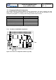
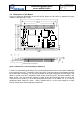
R1
R7 2 R7 3
R6 4
R6 6
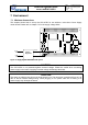
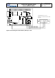
Figure 11: Location of configuration elements (bottom side)
7.2.2 Configuring DSP Clock Speed
R81 controls the setting of the CPUSPEED bit in the PLD's HWCFG register. The Flash File
System takes this bit to decide between 225 MHz and 300 MHz initialization. Application software
can also read this bit to determine the current setting. Please note that a 300 MHz DSP can be
configured for 225 MHz or 300 MHz operation, whereas a 225 MHz DSP can only be operated at
225 MHz.
R81 CPU clock EMIF clock
mounted with 10k
225 MHz 90 MHz
not mounted (default) 300 MHz 100 MHz
7.2.3 Configuring for HPI or McASP1 Usage
Using the McASP1 interface of the TMS320C6713 DSP is only possible when the HPI is disabled
and vice versa. The decision which interface is active is controlled by different components and is
not available for modification by the user. Default setting is to use the HPI. If McASP1 is to be
used, please contact ORSYS.
7.2.4 Configuring micro-line
®
Pin D30 Termination
By default, this pin has a 4.7k pull-up resistor (R72). This is necessary for using pin D30 as an
active-high RDY input with the micro-line
®
busmaster BSP. Alternatively, a pull-down resistor (R73)
can be mounted for usage of pin D30 as an active-low (e.g. /RDY) input.
R72 R73 usage of pin D30
mounted with 4.7k (default)
not mounted (default) Input with pull-up (e.g. RDY)
not mounted
mounted with 4.7k
input with pull-down (e.g. /RDY)
not mounted not mounted Any
7.2.5 Configuring for I
2
C interface #0 Operation
By default, the I
2
C interface #0 is disabled by hardware. and the corresponding two micro-line
®
connector pins can be used for FPGA I/O. If usage of I
2
C #0 is required, R64 and R66 have to be
mounted with 0. In this case, the FPGA design must not drive these signals.