
Corp. Computer Hardware User Manual


H
ARDWARE
R
EFERENCE
G
UIDE
MICRO
-
LINE
C6713CPU
Date : 28 November 2005
Doc. no. : C6713CPU_HRG
Iss./Rev : 1.1
Page : 2
Contents
1 PREFACE......................................................................................................................6
1.1
Document Organization.........................................................................................................6
1.2
Documentation Overview ......................................................................................................6
1.3
Notational conventions..........................................................................................................6
1.4
Trademarks.............................................................................................................................7
1.5
Revision History.....................................................................................................................8
2 HARDWARE OVERVIEW .............................................................................................9
2.1
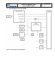
Block Diagram of the C6713CPU ........................................................................................10
2.2
Connectors ...........................................................................................................................12
2.2.1
micro-line
®
Connectors........................................................................................................ 12
2.2.2
JTAG Connector.................................................................................................................. 12
2.3
Interfaces and Hardware Components...............................................................................12
2.3.1
FPGA................................................................................................................................... 12
2.3.2
External Memory (on-board SDRAM).................................................................................. 13
2.3.3
Flash Memory...................................................................................................................... 14
2.3.4
PLD ..................................................................................................................................... 14
2.3.5
UART / RS-232 Interface .................................................................................................... 14
2.3.6
Temperature Sensor ........................................................................................................... 14
2.3.7
Reset Generator and Watchdog.......................................................................................... 15
2.3.8
External Flags (XF signals) ................................................................................................. 15
2.3.9
Power Supply of the Board.................................................................................................. 15
2.4
Status LED's .........................................................................................................................15
2.4.1
User Programmable LED's (PLD) ....................................................................................... 16
2.4.2
User Programmable LED (FPGA) ....................................................................................... 16
2.5
DSP peripherals....................................................................................................................16
2.5.1
Multichannel Audio Serial Ports (McASP) ........................................................................... 16
2.5.2
External Memory Interface (EMIF) ...................................................................................... 16
2.5.3
Inter Integrated Circuit (I
2
C) Interfaces................................................................................ 17
2.5.4
General Purpose Input / Output Pins (GPIO) ...................................................................... 17
2.5.5
Multi-channel Buffered Serial Ports (McBSP)...................................................................... 17
2.5.6
Timers ................................................................................................................................. 18
2.5.7
Host Port Interface (HPI) ..................................................................................................... 18
2.5.8
Interrupts ............................................................................................................................. 18
2.5.9
DMA .................................................................................................................................... 19
3 MEMORY MAPS AND DESCRIPTION OF THE PLD REGISTERS ...........................20
3.1
TMS320C6713 Memory Map ................................................................................................20
3.2
C6713CPU Address Map......................................................................................................21