
Installation Guide

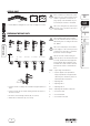

FR 5300
D
E
I
F
GB
Installation Instructions
Sanitary fitter
5
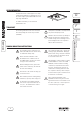
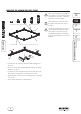
If the local drain is located in the corner
of the room, one of the foot units can be
shifted. To guarantee an adequate car
-
rying capacity of the FR 5300, only one
foot unit may be shifted, as illustrated.
Note I: The sliding block (A) shall be posi-
tioned as close as possible to the corner
of the FR 5300.
• Install additional sliding block (A, in scope of supply) (see note I).
SPECIAL CASE
2x1x
A
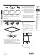
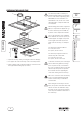
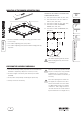
PREPARING THE FOOT UNITS
• Install foot units according to the installation height required (see
note I).
• Fasten foot caps (A) and sound isolating elements (B) to the re
-
spective foot units.
• Check the sound isolating elements (B) (see note II).
• Attach the foot extensions (E), if necessary.
The mounting height of the foot frame
has to be established with the supervisor
with binding force according to the metre
line. (OKFF).
Note I: The multi-purpose tool included
in the supply is to be exclusively used for
screwing on the foot units, as otherwise
the threads could be damaged.
Note II: The black sound isolating ele-
ments (B) have to be inserted in the blue
foot caps (A) with their hard, bright side
facing outward. After installation of the
foot frame the sound isolation elements
(B) must have surface contact with the
floor.
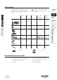
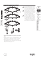
OKFF = Upper edge of finished floor
S = Special supports (not adjustable in
height, adjustments of height must be
effected by the customer by means of
substructures/floor structures.)
I = Adjusting unit I
II = Adjusting unit II
III = Adjusting unit III
III+V = Adjusting unit III with foot extension
C = Foot unit 13 mm
D = Foot unit 29 mm
E = Foot extension 35 mm
S I II III III + V
49 mm 63 - 77 mm 75 - 99 mm 97 - 131 mm 131 - 164 mm
OKFF
1 m
B
A
D
C
E
D