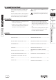
EINBAUANLEITUNG DUSCHWANNEN-FUSS-RAHMEN FR 5300 Installation instructions Instructions d’installation Instruzioni di montaggio Instrucciones de montaje
THE SHOWER TRAY FOOT FRAME This may damage your health or that of any other person using the shower tray. FR 5300 • Kaldewei reserves the right to change the contents of the mounting instructions without being obliged to inform any third parties. • Kaldewei reserves the right to modify and improve the technical system without being obliged to inform any third parties. Please read the attached additional information, if necessary.
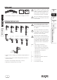
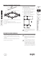
SCOPE OF SUPPLY Size 120/120 Size 50/180 Size 100/100 ARRONDO ZIRKON Size 100/100 CORNEZZA Foot units/ Foot extensions 8 each 8 each 12 each 8 each 8 each 5 5 9 6 4 4 4 4 3 3 - - - - 2 4 4 4 4 4 4 3 3 - - 8 2 2 4 4 4 4 5 Sliding blocks FR 5300 Corner joint Connecting rods 2 1 5 Rubber supporting pads Rubber holding profile 1x Multi-purpose tool 1x Installation instruction NOT INCLUDED IN THE SCOPE OF SUPPLY 2 • Earthing cable (green/yellow, min.
RECOMMENDATION As alternative for the central support of 2-component PUR foam Kaldewei recommends the use of the central support system MAS 5305 for shower trays larger than 90 cm. D GB For further information you are referred to www.kaldewei.com. F Kaldewei shall not assume any liability for damage incurred due to improper intermediate storage and for damage in transport resulting from the non-compliance with the above instructions.
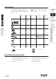
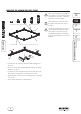
CUTTING THE CONNECTING RODS TO SIZE A L = S - 10 cm 36,1 cm 9 cm0 x 90 56 L = S - 7 cm R L = S - 10 cm L = S - 10 cm L = S - 10 cm L = S - 10 cm 90 x 90 L = S - 10 cm L = S - 10 cm S = Side length of this Kaldewei shower tray (A) L = Length of the connecting rod cut to size R = Radius 50 cm with shower tray ZIRKON/ radius 55 cm with shower tray ARRONDO PREPARATION OF THE SHOWER TRAY FOOT FRAME Note I: Mount the central foot units in the centre, as far as possible.
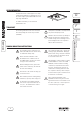
SPECIAL CASE 1x If the local drain is located in the corner of the room, one of the foot units can be shifted. To guarantee an adequate carrying capacity of the FR 5300, only one foot unit may be shifted, as illustrated. 2x A • Install additional sliding block (A, in scope of supply) (see note I). Note I: The sliding block (A) shall be positioned as close as possible to the corner of the FR 5300.
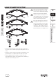
MOUNTING THE SHOWER TRAY FOOT FRAME S I II III III + V Note I: The multi-purpose tool included in the supply is to be exclusively used for screwing on the foot units, as otherwise the threads could be damaged. Note II: Attach the central foot units in the middle of the frame sides (legs), if possible. B Note III: The sliding blocks are only to be secured against being displaced again.
ALIGNING THE SHOWER TRAY FOOT FRAME B If the walls adjoining the foot frame are not angular, the supervisor has to be informed and remedial action to be taken (see DIN 18 202 Tolerances in building construction - Table 2 Angle tolerances. “The walls must not exceed the tolerance by more than 6 mm over a length of 1 m“). FR 5300 5x 5x 20 mm 10 mm 17 mm • Adjust the required height by means of the four foot units (A) at the corners of the foot frame by using the multi-purpose tool (see note I).
PREPARING THE SHOWER TRAY With mounting system frames larger than 90 cm, it is imperative to support the centre of the shower tray (at least 400 cm2) by means of two-component PUR foam. B FR 5300 Tip: Use the end strips of the cardboard box to fabricate an enclosure (A or B) for central support. The height corresponds to the height of the frame (D) less the depth of the shower tray (see transport box). For shower trays larger than 90 cm A= round, dia.
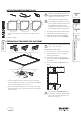
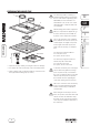
MOUNTING OF THE RUBBER SUPPORTING PADS A 1 = Size up to 120 cm x 120 cm (4x A, 4x C) 2 = Size from 140 cm x 70 cm to 180 cm x 100 cm (4x A, 4x B, 4x C) 3 = Size 150 cm x 150 cm (4x A, 8x B, 4x C) 4 = Size 100 cm x 100 cm ARRONDO/ ZIRKON (3x A, 2x B, 4x C) 5 = Size 100 cm x 100 cm CORNEZZA (3x A, 2x B, 5x C) FR 5300 1 2 • Check the FR 5300 for damage and soiling; repair and/or clean it, if necessary. • Place rubber supporting pads (B) and/or rubber holding profile (C) in position.
MOUNTING THE SHOWER TRAY • Put up the enclosures fabricated from the end strips of the cardboard box (A, alternatively MAS 5305 - see page 8) in the FR 5300 (if the shower trays are larger than 90 cm). Note II: Do not lay the earthing cable through the PUR foam or across the FR 5300. FR 5300 • Pile-up two-component PUR foam in the enclosure (A) at an excessive height (see note I). Note III: Make sure that the rubber supporting pads do not slip when placing the shower tray in position.
242.331 09/2010 Franz Kaldewei GmbH & Co. KG Beckumer Straße 33-35 59229 Ahlen Germany Tel. +49 2382 785 0 Fax +49 2382 785 200 Internet: www.kaldewei.