
Use and Care Manual


10 For Professional Technical Support call 1-844-242-2475
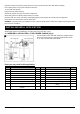
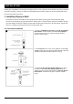
2. Install screen surround the foot valve, protect the foot valve
assembly from fish, trash, etc. Position the foot valve 5 feet
above bottom of well and It should also be at least 10 feet
below the water level in order to prevent the pump from
sucking air. (Fig 2)
3. Cement 1-1/4in. PVC MPT×S Male Adapter into 1-1/4 in.
PVC rigid Pipe. Install 1-1/4in.PVC TEE FPT×FPT×FPT to
adapter. One end of horizontal port install another 1-1/4in.
PVC MPT×S Male Adapter and 1-1/4 in. PVC rigid Pipe.
Add sections of pipes to reach the 1-1/4in. PVC Slip ×Slip
Union (optional). (Fig. 3)
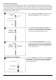
2. Well To Pump Connection
1. Thread 1-1/4in. PVC MPT×S Male Adapter into pump.
Cement a short horizontal 1-1/4 in. PVC rigid Pipe into
adapter. (Fig.1) (For model WPS05003K/WPS07503K)
Or thread 1in. ×1-1/4in. PVC MPT×S Reducer Male
Adapter into pump. Cement a short horizontal 1-1/4 in. PVC
rigid Pipe into adapter. (For Model WPS05002TK)
2. For pre-charged tank connection. Cement a 1-1/4in.
PVC Slip× Slip Union into a short horizontal 1-1/4 in. PVC
rigid Pipe. Slopes all inlet piping slightly upward from well to
the pump to prevent trapping air.(Fig.2)
For standard tank connection. Cement 1-1/4in. ×1-1/4in.
×3/4in. PVC S×S×FPT Reducer Tee Fitting into a short
horizontal 1-1/4 in. PVC rigid Pipe and cement another a
short horizontal 1-1/4 into the side of the tee fitting, then
install3/4in. MIP×1/2in.FIP Lead-Free Brass Hex Bushing
Fitting to the port of 3/4in, thread and another 1/2in.
MIP×1/8in.FIP Lead-Free Brass Hex Bushing Fitting to
the bushing fitting.