
User's Manual

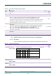


Table Of Contents
- 1. Introduction
- The PN7150 architecture overview
- 2. NCI Overview
- 3. DH interface
- 5. Initialization & Operation configuration
- 6. Reader/Writer Mode
- 6.1 T1T, T2T, MIFARE Ultralight, MIFARE Classic and MIFARE Plus tags
- 6.1.1 Access through the [NCI] Frame RF Interface
- 6.1.2 [PN7150-NCI] extension: TAG-CMD Interface
- 6.1.3 [PN7150-NCI] extension: Payload structure of the TAG-CMD RF Interface
- 6.1.4 [PN7150-NCI] extension: REQs & RSPs rules
- 6.1.5 [PN7150-NCI] extension: List of REQs & RSPs
- 6.1.6 [PN7150-NCI] extension: raw data exchange REQs & RSPs
- 6.1.7 [PN7150-NCI] extension: T2T & MFU REQs & RSPs
- 6.1.8 [PN7150-NCI] extension: MIFARE Classic REQs & RSPs
- 6.1.9 Access through the TAG-CMD RF Interface
- 6.2 T3T tag
- 6.3 T4T & ISO-DEP Tags/Cards
- 6.3.1 Access through the Frame RF Interface
- 6.3.2 Access through the ISO-DEP RF Interface
- 6.3.3 [PN7150-NCI] extension: Presence check Command/Response
- 6.3.4 [PN7150-NCI] extension: S-Block Command/Response
- 6.3.5 [PN7150-NCI] extension: WTX notification
- 6.3.6 [PN7150-NCI] extension: Higher bit rates in Poll NFC-A & NFC-B
- 6.4 [PN7150-NCI] extension: 15693 & I-Code tags
- 6.5 [PN7150-NCI] extension: KOVIO tags
- 6.1 T1T, T2T, MIFARE Ultralight, MIFARE Classic and MIFARE Plus tags
- 7. Card Emulation Mode
- 8. P2P Initiator & Target Mode
- 9. RF Discovery Management
- 9.1 RF Discovery functionalities
- 9.2 NFC FORUM Profile as defined in [NCI]
- 9.3 [PN7150-NCI] extension: additional technologies not yet supported by the NFC FORUM
- 9.4 [PN7150-NCI] extension: Low Power Card Detector (LPCD) Mode
- 9.5 [PN7150-NCI] extension: EMVCo Profile in Poll & Listen Modes
- 9.6 [PN7150-NCI] extension: Power optimization
- 10. Configurations
- 11. Test Mode
- 12. PN7150 Practical approach

U
M10936
P
N7150 User Manual
UM
10936 All information provided in this document is subject to legal disclaimers.
U
ser manual
CO
MPANY PUBLIC
Rev. 2.0 — 6 November 2020
348120
97 of 127
T
able 93. TEST_PRBS_RSP
G
ID
O
ID
N
umbers of
p
arameter(s)
D
escription
1111b 0x30 1 PN7150 reports if the TEST_PRBS_CMD is successful or not.
Table 94. TEST_PRBS_RSP parameters
Payload Field(s) Length Value/Description
ST
ATUS 1 Octet
0x
00 STATUS_OK
0x
06 STATUS_SYNTAX_ERROR
0x09 STATUS_INVALID_PARAM
O
thers Forbidden
!
T
he only way to stop the on-going PRBS pattern generation is to apply a HW
reset (through the VEN pin).
11.3 TEST_ANTENNA_CMD/RSP
T
his command is used to execute the antenna self-test measurements, which allow to
check that all the discrete components connected between PN7150 and the contactless
antenna are properly soldered on the PCB.
Four different measurements are necessary to check the correct connection of all the
discrete components, therefore a complete Antenna Self-Test requires to execute the
TEST_ANTENNA_CMD 4 consecutive times, with a different set of parameters for each
execution.
Table 95. TEST_ANTENNA_CMD
G
ID
O
ID
Numbers of
p
arameter(s)
D
escription
1111b 0x
3D 2-4 Command to execute antenna self-test measurements.
T
able 96. TEST_ANTENNA_CMD parameters
P
ayload Field(s)
L
ength
V
alue/Description
Measurement ID 1 Octet
0x
01 TxLDO current measurement
0x
02 AGC value reading
0x
04
AGC value reading with fixed
NFCLD level
0x20 Switch RF Field On/Off
0x
03,
0x05-0x1F,
0x21-0xFF
RFU
P
arameters of
individual test
measurement
1-3
Octets
For individual test parameters please refer to →Table 98