
User's Manual

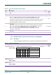


Table Of Contents
- 1. Introduction
- The PN7150 architecture overview
- 2. NCI Overview
- 3. DH interface
- 5. Initialization & Operation configuration
- 6. Reader/Writer Mode
- 6.1 T1T, T2T, MIFARE Ultralight, MIFARE Classic and MIFARE Plus tags
- 6.1.1 Access through the [NCI] Frame RF Interface
- 6.1.2 [PN7150-NCI] extension: TAG-CMD Interface
- 6.1.3 [PN7150-NCI] extension: Payload structure of the TAG-CMD RF Interface
- 6.1.4 [PN7150-NCI] extension: REQs & RSPs rules
- 6.1.5 [PN7150-NCI] extension: List of REQs & RSPs
- 6.1.6 [PN7150-NCI] extension: raw data exchange REQs & RSPs
- 6.1.7 [PN7150-NCI] extension: T2T & MFU REQs & RSPs
- 6.1.8 [PN7150-NCI] extension: MIFARE Classic REQs & RSPs
- 6.1.9 Access through the TAG-CMD RF Interface
- 6.2 T3T tag
- 6.3 T4T & ISO-DEP Tags/Cards
- 6.3.1 Access through the Frame RF Interface
- 6.3.2 Access through the ISO-DEP RF Interface
- 6.3.3 [PN7150-NCI] extension: Presence check Command/Response
- 6.3.4 [PN7150-NCI] extension: S-Block Command/Response
- 6.3.5 [PN7150-NCI] extension: WTX notification
- 6.3.6 [PN7150-NCI] extension: Higher bit rates in Poll NFC-A & NFC-B
- 6.4 [PN7150-NCI] extension: 15693 & I-Code tags
- 6.5 [PN7150-NCI] extension: KOVIO tags
- 6.1 T1T, T2T, MIFARE Ultralight, MIFARE Classic and MIFARE Plus tags
- 7. Card Emulation Mode
- 8. P2P Initiator & Target Mode
- 9. RF Discovery Management
- 9.1 RF Discovery functionalities
- 9.2 NFC FORUM Profile as defined in [NCI]
- 9.3 [PN7150-NCI] extension: additional technologies not yet supported by the NFC FORUM
- 9.4 [PN7150-NCI] extension: Low Power Card Detector (LPCD) Mode
- 9.5 [PN7150-NCI] extension: EMVCo Profile in Poll & Listen Modes
- 9.6 [PN7150-NCI] extension: Power optimization
- 10. Configurations
- 11. Test Mode
- 12. PN7150 Practical approach

U
M10936
P
N7150 User Manual
UM
10936 All information provided in this document is subject to legal disclaimers.
U
ser manual
CO
MPANY PUBLIC
Rev. 2.0 — 6 November 2020
348120
94 of 127
Na
me & Rights
D
escription
Ex
t. Tag
L
en.
D
efault
Value
T
he list of transition IDs and the appropriate values for
the Register offset & its value is available in [AN 11755],
as referenced in →15
!
CO
RE_SET_CONFIG_CMD command to set RF Transitions triggers internal
EEPROM memory page write operation. To prevent memory corruption, any
interruption of this command (between CORE_SET_CONFIG_CMD and
CORE_SET_CONFIG_RSP) by hardware reset or power off MUST be
prevented.
Thus, it is recommended to:
- Prevent re-applying RF Transitions parameters when not required (those
parameters been stored in non-volatile memory, there are persistent
even in case NCI CORE_RESET_CMD with option “reset configuration”
is applied).
- Split the RF Transition settings into several CORE_SET_CONFIG_CMD
commands to limit the time for the command treatment inside PN7150
(CORE_SET_CONFIG_CMD with only one RF Transition takes 2.7ms,
5.4ms in the specific case where the RF parameter resides in 2 separate
Flash memory blocks)
- Avoid mixing RF Transition parameters with other parameters (not
starting with address 0xA00D) in a same CORE_SET_CONFIG_CMD
command
!
P
N7150B0HN/C11006 version only allows recovering from such memory
corruption. Refer to 4.3.8.3 for more details about this mechanism.
!
P
N7150 only supports RF_TRANSITION_CFG with command
CORE_SET_CONFIG_CMD. CORE_GET_CONFIG_CMD is not supported.
To read out the values a specific command RF_GET_TRANSITION_CMD is
to be used.
T
able 87. RF_GET_TRANSITION_CMD
G
ID
O
ID
N
umbers of
parameter(s)
D
escription
1111b 0x
14 2 The DH asks to read out the value of an RF Transition
T
able 88. RF_ GET_TRANSITION_CMD parameters
P
ayload Field(s)
L
ength
V
alue/Description
R
F Transition ID 1 Octet RF Transition Identifier