
User's Manual

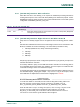


Table Of Contents
- 1. Introduction
- The PN7150 architecture overview
- 2. NCI Overview
- 3. DH interface
- 5. Initialization & Operation configuration
- 6. Reader/Writer Mode
- 6.1 T1T, T2T, MIFARE Ultralight, MIFARE Classic and MIFARE Plus tags
- 6.1.1 Access through the [NCI] Frame RF Interface
- 6.1.2 [PN7150-NCI] extension: TAG-CMD Interface
- 6.1.3 [PN7150-NCI] extension: Payload structure of the TAG-CMD RF Interface
- 6.1.4 [PN7150-NCI] extension: REQs & RSPs rules
- 6.1.5 [PN7150-NCI] extension: List of REQs & RSPs
- 6.1.6 [PN7150-NCI] extension: raw data exchange REQs & RSPs
- 6.1.7 [PN7150-NCI] extension: T2T & MFU REQs & RSPs
- 6.1.8 [PN7150-NCI] extension: MIFARE Classic REQs & RSPs
- 6.1.9 Access through the TAG-CMD RF Interface
- 6.2 T3T tag
- 6.3 T4T & ISO-DEP Tags/Cards
- 6.3.1 Access through the Frame RF Interface
- 6.3.2 Access through the ISO-DEP RF Interface
- 6.3.3 [PN7150-NCI] extension: Presence check Command/Response
- 6.3.4 [PN7150-NCI] extension: S-Block Command/Response
- 6.3.5 [PN7150-NCI] extension: WTX notification
- 6.3.6 [PN7150-NCI] extension: Higher bit rates in Poll NFC-A & NFC-B
- 6.4 [PN7150-NCI] extension: 15693 & I-Code tags
- 6.5 [PN7150-NCI] extension: KOVIO tags
- 6.1 T1T, T2T, MIFARE Ultralight, MIFARE Classic and MIFARE Plus tags
- 7. Card Emulation Mode
- 8. P2P Initiator & Target Mode
- 9. RF Discovery Management
- 9.1 RF Discovery functionalities
- 9.2 NFC FORUM Profile as defined in [NCI]
- 9.3 [PN7150-NCI] extension: additional technologies not yet supported by the NFC FORUM
- 9.4 [PN7150-NCI] extension: Low Power Card Detector (LPCD) Mode
- 9.5 [PN7150-NCI] extension: EMVCo Profile in Poll & Listen Modes
- 9.6 [PN7150-NCI] extension: Power optimization
- 10. Configurations
- 11. Test Mode
- 12. PN7150 Practical approach

U
M10936
P
N7150 User Manual
UM
10936 All information provided in this document is subject to legal disclaimers.
U
ser manual
CO
MPANY PUBLIC
Rev. 2.0 — 6 November 2020
348120
66 of 127
C
ommand
M
ain Parameters
V
alues
L
B_APPLICATION_DATA
LB_SFGI
LB
_ADC_FO
L
I_FWI
L
B_H_INFO_RESP
1
LI
_BIT_RATE
RF_DISCOVER_CMD RF Technology & Mode NFC_B_PASSIVE_LISTEN_MODE
1
t
his parameter is not active in PN7150: it can be read/written, but PN7150 will always
behave with empty Higher Layer – Response field in the ATTRIB response, whatever the
v
alue written by the DH to that parameter.
7.2 T3T card emulation through NFC-F
7.
2.1 Configuring the T3T card emulation
A
s described in the NFC specification, several Listen F parameters exist to set up T3T with
NCI commands.
T
able 69. Values to configure the T3T on DH
ID Length Values and description
LF
_T3T_MAX 1 byte
0 – 16, defines the maximum amount of
LF_T3T_IDENTIFIERS supported by the NFCC.
PN7150 supports four maximum.
LF_T3T_IDENTIFIERS_1 - 4 10 bytes
Bytes 0 and 1 define the SC to be used by the T3T.
Bytes 2 – 10 define the NFCID2 value to be used.
7.
2.2 Access through the Frame RF Interface
T
he Frame RF interface allows emulating a T3T card, assuming that the DH is able to
manage the T3T protocol on its own.
H
ere are the commands and configuration parameters to prepare the T3T Card Emulation
for technology NFC-F through the Frame RF Interface:
Table 70. Configuration seq. for ISO-DEP/NFC-A Card Emulation in the DH over Frame RF
Interface
Command Main Parameters Values
RF
_DISCOVER_MAP_CMD *
RF Protocol PROTOCOL_T3T
M
ode Listen
RF Interface Frame
CO
RE_SET_CONFIG_CMD
LF_T3T_MAX
See above, used to set SC,
NFCID2
LF
_T3T_IDENTIFIERS_X
RF_DISCOVER_CMD RF Technology & Mode NFC_F_PASSIVE_LISTEN_MODE