
User's Manual

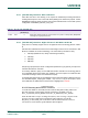


Table Of Contents
- 1. Introduction
- The PN7150 architecture overview
- 2. NCI Overview
- 3. DH interface
- 5. Initialization & Operation configuration
- 6. Reader/Writer Mode
- 6.1 T1T, T2T, MIFARE Ultralight, MIFARE Classic and MIFARE Plus tags
- 6.1.1 Access through the [NCI] Frame RF Interface
- 6.1.2 [PN7150-NCI] extension: TAG-CMD Interface
- 6.1.3 [PN7150-NCI] extension: Payload structure of the TAG-CMD RF Interface
- 6.1.4 [PN7150-NCI] extension: REQs & RSPs rules
- 6.1.5 [PN7150-NCI] extension: List of REQs & RSPs
- 6.1.6 [PN7150-NCI] extension: raw data exchange REQs & RSPs
- 6.1.7 [PN7150-NCI] extension: T2T & MFU REQs & RSPs
- 6.1.8 [PN7150-NCI] extension: MIFARE Classic REQs & RSPs
- 6.1.9 Access through the TAG-CMD RF Interface
- 6.2 T3T tag
- 6.3 T4T & ISO-DEP Tags/Cards
- 6.3.1 Access through the Frame RF Interface
- 6.3.2 Access through the ISO-DEP RF Interface
- 6.3.3 [PN7150-NCI] extension: Presence check Command/Response
- 6.3.4 [PN7150-NCI] extension: S-Block Command/Response
- 6.3.5 [PN7150-NCI] extension: WTX notification
- 6.3.6 [PN7150-NCI] extension: Higher bit rates in Poll NFC-A & NFC-B
- 6.4 [PN7150-NCI] extension: 15693 & I-Code tags
- 6.5 [PN7150-NCI] extension: KOVIO tags
- 6.1 T1T, T2T, MIFARE Ultralight, MIFARE Classic and MIFARE Plus tags
- 7. Card Emulation Mode
- 8. P2P Initiator & Target Mode
- 9. RF Discovery Management
- 9.1 RF Discovery functionalities
- 9.2 NFC FORUM Profile as defined in [NCI]
- 9.3 [PN7150-NCI] extension: additional technologies not yet supported by the NFC FORUM
- 9.4 [PN7150-NCI] extension: Low Power Card Detector (LPCD) Mode
- 9.5 [PN7150-NCI] extension: EMVCo Profile in Poll & Listen Modes
- 9.6 [PN7150-NCI] extension: Power optimization
- 10. Configurations
- 11. Test Mode
- 12. PN7150 Practical approach

U
M10936
P
N7150 User Manual
UM
10936 All information provided in this document is subject to legal disclaimers.
U
ser manual
CO
MPANY PUBLIC
Rev. 2.0 — 6 November 2020
348120
61 of 127
T
able 63. Config. seq. for R/W of NFC-15693 through the Frame RF Interface
Command Main Parameters Values
RF
_DISCOVER_MAP_CMD *
RF Protocol PROTOCOL_15693
M
ode Poll
RF Interface Frame RF
RF
_DISCOVER_CMD RF Technology & Mode NFC_15693_PASSIVE_POLL_MODE
* No
te: RF_DISCOVER_MAP_CMD is optional since the mapping to Frame RF Intf. is done by default
6.
4.2 [PN7150-NCI] extension: Specific parameters for NFC_15693 Poll Mode
O
nce PN7150 detects and activates a remote NFC Endpoint based on NFC-15693,
PN7150 will activate the Frame RF Interface, providing the following activation parameters:
T
able 64. Specific parameters for NFC_15693 Poll Mode
Parameter Length Description
F
LAGS 1 Octet 1
st
B
yte of the Inventory Response
DSFID 1 Octet 2
nd
Byte of the Inventory Response
UI
D 8 Octets 3
rd
B
yte to last Byte of the Inventory Response
6.
4.3 [PN7150-NCI] extension: Data Mapping between the DH and RF
D
ata from the DH to RF
The NCI Data Message corresponds to the Request Format defined in [ISO15693-3]
Section 7.3.
After receiving a Data Message from the DH, the PN7150 appends the appropriate EoD,
SOF and EOF and then sends the result in an RF Frame in NFC-15693 technology to the
Remote NFC Endpoint.
The following figure illustrates the mapping between the NCI Data Message Format and
the RF frame when sending the RF frame to the Remote NFC Endpoint. This figure shows
the case where NCI Segmentation and Reassembly feature is not used.
Payload [EoD]
CRC_1 CRC_2
Data Packet Header Payload
RF Frame
Data Packet
FLAGS CMD PARAM DATASOF EOF
F
ig 33. Format for Frame RF Interface (NFC-15693) for Transmission
A
lthough the Frame RF interface is defined to be a transparent interface where the NFCC
does not parse/modify the Bytes transmitted by the DH, the following exceptions occur: