
User's Manual


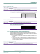
Table Of Contents
- 1. Introduction
- The PN7150 architecture overview
- 2. NCI Overview
- 3. DH interface
- 5. Initialization & Operation configuration
- 6. Reader/Writer Mode
- 6.1 T1T, T2T, MIFARE Ultralight, MIFARE Classic and MIFARE Plus tags
- 6.1.1 Access through the [NCI] Frame RF Interface
- 6.1.2 [PN7150-NCI] extension: TAG-CMD Interface
- 6.1.3 [PN7150-NCI] extension: Payload structure of the TAG-CMD RF Interface
- 6.1.4 [PN7150-NCI] extension: REQs & RSPs rules
- 6.1.5 [PN7150-NCI] extension: List of REQs & RSPs
- 6.1.6 [PN7150-NCI] extension: raw data exchange REQs & RSPs
- 6.1.7 [PN7150-NCI] extension: T2T & MFU REQs & RSPs
- 6.1.8 [PN7150-NCI] extension: MIFARE Classic REQs & RSPs
- 6.1.9 Access through the TAG-CMD RF Interface
- 6.2 T3T tag
- 6.3 T4T & ISO-DEP Tags/Cards
- 6.3.1 Access through the Frame RF Interface
- 6.3.2 Access through the ISO-DEP RF Interface
- 6.3.3 [PN7150-NCI] extension: Presence check Command/Response
- 6.3.4 [PN7150-NCI] extension: S-Block Command/Response
- 6.3.5 [PN7150-NCI] extension: WTX notification
- 6.3.6 [PN7150-NCI] extension: Higher bit rates in Poll NFC-A & NFC-B
- 6.4 [PN7150-NCI] extension: 15693 & I-Code tags
- 6.5 [PN7150-NCI] extension: KOVIO tags
- 6.1 T1T, T2T, MIFARE Ultralight, MIFARE Classic and MIFARE Plus tags
- 7. Card Emulation Mode
- 8. P2P Initiator & Target Mode
- 9. RF Discovery Management
- 9.1 RF Discovery functionalities
- 9.2 NFC FORUM Profile as defined in [NCI]
- 9.3 [PN7150-NCI] extension: additional technologies not yet supported by the NFC FORUM
- 9.4 [PN7150-NCI] extension: Low Power Card Detector (LPCD) Mode
- 9.5 [PN7150-NCI] extension: EMVCo Profile in Poll & Listen Modes
- 9.6 [PN7150-NCI] extension: Power optimization
- 10. Configurations
- 11. Test Mode
- 12. PN7150 Practical approach

U
M10936
P
N7150 User Manual
UM
10936 All information provided in this document is subject to legal disclaimers.
U
ser manual
CO
MPANY PUBLIC
Rev. 2.0 — 6 November 2020
348120
48 of 127
Conn ID
Msg
Type
Byte 0
RFU
Byte 1
Payload Length
Byte 2
PAYLOAD
REQ ID
Byte 3
Parameter 1
(optional)
Byte 4
Parameter 2
(optional)
Byte 5
DATA (if any)
RSP ID
Byte 3
RF StatusDATA (if any)
Byte n
REQs Frame structure
RSPs Frame structure
NCI data packet structure
Conn ID
Msg
Type
Byte 0
RFU
Byte 1
Payload Length
Byte 2
Conn ID
Msg
Type
Byte 0
RFU
Byte 1
Payload Length
Byte 2
Fig 31. Data message payload for the TAG-CMD Interface
N
ote: REQs and RSPs don’t share exactly the same structure:
R
EQs: Although illustrated with 2 parameters on the figure above, REQs may have no
parameters or only one. Some REQuests might also need parameters bigger than 1 Byte.
Parsing The REQ ID is the way to know how many parameters follow and how long they
are.
RSPs: there are no parameters in ReSPonses. A Byte is added at the end of the payload
(after the DATA field) to inform the DH on the RF status (to report RF errors if they were
some). The Status codes used are the following:
Table 29. TAG-CMD RF Status code
Va
lue
D
escription
0x00 STATUS_OK
0x03 STATUS_FAILED
0
xB0 RF_TRANSMISSION_ERROR
0xB1 RF_PROTOCOL_ERROR
0
xB2 RF_TIMEOUT_ERROR
Others Forbidden
6.
1.4 [PN7150-NCI] extension: REQs & RSPs rules
A
REQ command is always going from DH to RF, through the NFCC.
A RSP response is always going from the RF to the DH, through the NFCC
The DH SHALL wait until it has received a RSP associated to a REQ before it can send a
new REQ.