
User's Manual
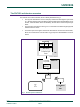
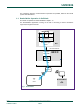
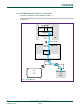


Table Of Contents
- 1. Introduction
- The PN7150 architecture overview
- 2. NCI Overview
- 3. DH interface
- 5. Initialization & Operation configuration
- 6. Reader/Writer Mode
- 6.1 T1T, T2T, MIFARE Ultralight, MIFARE Classic and MIFARE Plus tags
- 6.1.1 Access through the [NCI] Frame RF Interface
- 6.1.2 [PN7150-NCI] extension: TAG-CMD Interface
- 6.1.3 [PN7150-NCI] extension: Payload structure of the TAG-CMD RF Interface
- 6.1.4 [PN7150-NCI] extension: REQs & RSPs rules
- 6.1.5 [PN7150-NCI] extension: List of REQs & RSPs
- 6.1.6 [PN7150-NCI] extension: raw data exchange REQs & RSPs
- 6.1.7 [PN7150-NCI] extension: T2T & MFU REQs & RSPs
- 6.1.8 [PN7150-NCI] extension: MIFARE Classic REQs & RSPs
- 6.1.9 Access through the TAG-CMD RF Interface
- 6.2 T3T tag
- 6.3 T4T & ISO-DEP Tags/Cards
- 6.3.1 Access through the Frame RF Interface
- 6.3.2 Access through the ISO-DEP RF Interface
- 6.3.3 [PN7150-NCI] extension: Presence check Command/Response
- 6.3.4 [PN7150-NCI] extension: S-Block Command/Response
- 6.3.5 [PN7150-NCI] extension: WTX notification
- 6.3.6 [PN7150-NCI] extension: Higher bit rates in Poll NFC-A & NFC-B
- 6.4 [PN7150-NCI] extension: 15693 & I-Code tags
- 6.5 [PN7150-NCI] extension: KOVIO tags
- 6.1 T1T, T2T, MIFARE Ultralight, MIFARE Classic and MIFARE Plus tags
- 7. Card Emulation Mode
- 8. P2P Initiator & Target Mode
- 9. RF Discovery Management
- 9.1 RF Discovery functionalities
- 9.2 NFC FORUM Profile as defined in [NCI]
- 9.3 [PN7150-NCI] extension: additional technologies not yet supported by the NFC FORUM
- 9.4 [PN7150-NCI] extension: Low Power Card Detector (LPCD) Mode
- 9.5 [PN7150-NCI] extension: EMVCo Profile in Poll & Listen Modes
- 9.6 [PN7150-NCI] extension: Power optimization
- 10. Configurations
- 11. Test Mode
- 12. PN7150 Practical approach

U
M10936
P
N7150 User Manual
UM
10936 All information provided in this document is subject to legal disclaimers.
U
ser manual
CO
MPANY PUBLIC
Rev. 2.0 — 6 November 2020
348120
4 of 127
T
he PN7150 architecture overview
T
he PN7150 is an NFC Controller, which is briefly described in Fig 1:
• The top part describes the Device Host (DH) architecture with Higher Layer Driver
(e.g. Android stack) hosting the different kind of applications (Reader/Writer, Peer
to Peer, Card Emulation in the DH-NFCEE), the NCI driver & the transport layer
driver.
• The PN7150 is the NFCC in the Fig 1. It is connected to the DH through a physical
interface which is an I2C.
•
The bottom part of the figure contains the RF antenna connected to the PN71
5
0,
which can communicate over RF with a Tag (Card) and a Reader/Writer or a Peer
device.
Antenna
DH
NFCC
NCI driver
RF
Card
Emulat°
Transport
Layer FW
NCI
firmware
Transport layer
driver
TAG
or
Card
Reader/Writer
or
P2P
Reader
/ Writer
P2P
DH-NFCEE
I²C host interface
Fig 1. PN7150 system architecture