
User's Manual
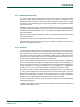


Table Of Contents
- 1. Introduction
- The PN7150 architecture overview
- 2. NCI Overview
- 3. DH interface
- 5. Initialization & Operation configuration
- 6. Reader/Writer Mode
- 6.1 T1T, T2T, MIFARE Ultralight, MIFARE Classic and MIFARE Plus tags
- 6.1.1 Access through the [NCI] Frame RF Interface
- 6.1.2 [PN7150-NCI] extension: TAG-CMD Interface
- 6.1.3 [PN7150-NCI] extension: Payload structure of the TAG-CMD RF Interface
- 6.1.4 [PN7150-NCI] extension: REQs & RSPs rules
- 6.1.5 [PN7150-NCI] extension: List of REQs & RSPs
- 6.1.6 [PN7150-NCI] extension: raw data exchange REQs & RSPs
- 6.1.7 [PN7150-NCI] extension: T2T & MFU REQs & RSPs
- 6.1.8 [PN7150-NCI] extension: MIFARE Classic REQs & RSPs
- 6.1.9 Access through the TAG-CMD RF Interface
- 6.2 T3T tag
- 6.3 T4T & ISO-DEP Tags/Cards
- 6.3.1 Access through the Frame RF Interface
- 6.3.2 Access through the ISO-DEP RF Interface
- 6.3.3 [PN7150-NCI] extension: Presence check Command/Response
- 6.3.4 [PN7150-NCI] extension: S-Block Command/Response
- 6.3.5 [PN7150-NCI] extension: WTX notification
- 6.3.6 [PN7150-NCI] extension: Higher bit rates in Poll NFC-A & NFC-B
- 6.4 [PN7150-NCI] extension: 15693 & I-Code tags
- 6.5 [PN7150-NCI] extension: KOVIO tags
- 6.1 T1T, T2T, MIFARE Ultralight, MIFARE Classic and MIFARE Plus tags
- 7. Card Emulation Mode
- 8. P2P Initiator & Target Mode
- 9. RF Discovery Management
- 9.1 RF Discovery functionalities
- 9.2 NFC FORUM Profile as defined in [NCI]
- 9.3 [PN7150-NCI] extension: additional technologies not yet supported by the NFC FORUM
- 9.4 [PN7150-NCI] extension: Low Power Card Detector (LPCD) Mode
- 9.5 [PN7150-NCI] extension: EMVCo Profile in Poll & Listen Modes
- 9.6 [PN7150-NCI] extension: Power optimization
- 10. Configurations
- 11. Test Mode
- 12. PN7150 Practical approach

U
M10936
P
N7150 User Manual
UM
10936 All information provided in this document is subject to legal disclaimers.
U
ser manual
CO
MPANY PUBLIC
Rev. 2.0 — 6 November 2020
348120
21 of 127
A
s indicated on Fig 15, in case the PN7150 requests a data transfer by raising the IRQ pin
and the DH tries to initiate a write sequence by positioning the write bit to 0b, the PN7150
keeps the IRQ active until the DH starts a read sequence.
The DH is not allowed to proceed with a write sequence once the PN7150 has set the IRQ
pin to its active value (logical ‘1’ in Fig 15).
If PN7150 has another message ready to be sent to the DH before the end of the on-going
Read Sequence, the IRQ pin will be first deactivated at the end of the on-going Read
Sequence and then re-activated to notify to the DH that a new message has to be read.
3.5 Split mode
T
he PN7150 supports the interruption of a frame transfer, as defined in [I²C]. This feature
is only available in Read Mode; it is forbidden to use it in Write Mode.
This can be useful in a system where the I²C bus is shared between several peripherals:
it allows the host to stop an on-going exchange, to switch to another peripheral (with a
different slave address) and then to resume the communication with the PN7150.
Another typical use-case for the split mode is to have the DH reading first the NCI packet
header, to know what the Payload length is. The DH can then allocate a buffer with an
appropriate size and read the payload data to fill this buffer. This use-case is represented
on Fig 16:
SCL
DH can split the I²C Read transfer
NCI Header
Byte 0
NCI Header
Byte 1
NCI Payload
Length
NCI Payload
Byte n
I²C Slave Address
+ R/W bit = 1b
SDA
IRQ
I²C Start
I²C Stop
I²C Stop
I²C Start
NCI Payload
Byte 0
I²C Slave Address
+ R/W bit = 1b
F
ig 16. I²C Read sequence with split mode
3.6 Optional transport fragmentation
PN
7150 comes with an optional transport fragmentation on I²C, which can be
enabled/disabled thanks to bit b4 in IRQ_POLARITY_CFG (see →10.1).
This fragmentation can only be used from the DH to the PN7150: there is no fragmentation
available from the PN7150 to the DH.
This fragmentation is purely implemented at the I²C transport layer and does not interfere
with NCI segmentation, which remains possible on top.