
User's Manual
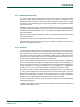


Table Of Contents
- 1. Introduction
- The PN7150 architecture overview
- 2. NCI Overview
- 3. DH interface
- 5. Initialization & Operation configuration
- 6. Reader/Writer Mode
- 6.1 T1T, T2T, MIFARE Ultralight, MIFARE Classic and MIFARE Plus tags
- 6.1.1 Access through the [NCI] Frame RF Interface
- 6.1.2 [PN7150-NCI] extension: TAG-CMD Interface
- 6.1.3 [PN7150-NCI] extension: Payload structure of the TAG-CMD RF Interface
- 6.1.4 [PN7150-NCI] extension: REQs & RSPs rules
- 6.1.5 [PN7150-NCI] extension: List of REQs & RSPs
- 6.1.6 [PN7150-NCI] extension: raw data exchange REQs & RSPs
- 6.1.7 [PN7150-NCI] extension: T2T & MFU REQs & RSPs
- 6.1.8 [PN7150-NCI] extension: MIFARE Classic REQs & RSPs
- 6.1.9 Access through the TAG-CMD RF Interface
- 6.2 T3T tag
- 6.3 T4T & ISO-DEP Tags/Cards
- 6.3.1 Access through the Frame RF Interface
- 6.3.2 Access through the ISO-DEP RF Interface
- 6.3.3 [PN7150-NCI] extension: Presence check Command/Response
- 6.3.4 [PN7150-NCI] extension: S-Block Command/Response
- 6.3.5 [PN7150-NCI] extension: WTX notification
- 6.3.6 [PN7150-NCI] extension: Higher bit rates in Poll NFC-A & NFC-B
- 6.4 [PN7150-NCI] extension: 15693 & I-Code tags
- 6.5 [PN7150-NCI] extension: KOVIO tags
- 6.1 T1T, T2T, MIFARE Ultralight, MIFARE Classic and MIFARE Plus tags
- 7. Card Emulation Mode
- 8. P2P Initiator & Target Mode
- 9. RF Discovery Management
- 9.1 RF Discovery functionalities
- 9.2 NFC FORUM Profile as defined in [NCI]
- 9.3 [PN7150-NCI] extension: additional technologies not yet supported by the NFC FORUM
- 9.4 [PN7150-NCI] extension: Low Power Card Detector (LPCD) Mode
- 9.5 [PN7150-NCI] extension: EMVCo Profile in Poll & Listen Modes
- 9.6 [PN7150-NCI] extension: Power optimization
- 10. Configurations
- 11. Test Mode
- 12. PN7150 Practical approach

U
M10936
P
N7150 User Manual
UM
10936 All information provided in this document is subject to legal disclaimers.
U
ser manual
CO
MPANY PUBLIC
Rev. 2.0 — 6 November 2020
348120
20 of 127
I
t may send an I²C NACK (negative acknowledge) when none of the buffers used by the
NCI core in the PN7150 is free, which may happen in case PN7150 is in standby mode. If
one single byte of a complete NCI frame is NACKed by the PN7150, the DH has to re-
send the complete NCI frame and not only this single byte.
SCL
NCI Header
Byte 0
NCI Header
Byte 1
NCI Payload
Length
NCI Payload
Byte 0
NCI Payload
Byte n-2
NCI Payload
Byte n-1
NCI Payload
Byte n
I²C Slave Address
+ R/W bit = 0b
SDA
IRQ
I²C Start
I²C Stop
F
ig 14. I²C Write sequence
!
It may happen that PN7150 has an NCI Message ready to be sent to the DH while
it is receiving another NCI Message from the DH. In such a condition, the IRQ pin
will be raised somewhere during the Write Sequence: this is not an error and has
to be accepted by the DH: once the Write Sequence is completed, the DH has to
start a Read Sequence (see →3.4).
3
.4 Read Sequence from the DH
The
DH shall never initiate a spontaneous I²C read request. The DH shall wait until it is
triggered by the PN7150.
To trigger the DH, the PN7150 generates a logical transition from Low to High on its IRQ
pin (if the IRQ pin is configured to be active High; see configuration chapter →10.1). So
after writing any NCI command, the DH shall wait until the PN7150 raises its IRQ pin.
The DH can then transmit a Read request to fetch the NCI answer from the PN7150. When
the PN7150 needs to send a spontaneous notification to the DH (for instance an RF
Interface activation notification), the PN7150 raises the IRQ pin and the DH performs a
normal read as described above.
A DH Read Sequence always starts by the sending of the PN7150 I²C Slave Address
followed by the read bit (logical ‘1’). Then the DH I²C interface sends an ACK back to the
PN7150 for each data Byte received.
Fig 15 is an example where the IRQ is raised so the DH can proceed a read.
DH knows how often
to Apply the clock
SCL
If the DH sends more
clocks, zeros will be sent
NCI Header
Byte 0
NCI Header
Byte 1
NCI Payload
Length
NCI Payload
Byte 0
NCI Payload
Byte n-2
NCI Payload
Byte n-1
NCI Payload
Byte n
I²C Slave Address
+ R/W bit = 1b
SDA
IRQ
NFCC requests
a transfer
All data has been
read, IRQ is reset
If NFCC requests a transfer, but DH sets
R/W bit to 0b, IRQ will remain high.
I²C Start
I²C Stop
F
ig 15. I²C Read sequence