
User's Manual
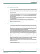


Table Of Contents
- 1. Introduction
- The PN7150 architecture overview
- 2. NCI Overview
- 3. DH interface
- 5. Initialization & Operation configuration
- 6. Reader/Writer Mode
- 6.1 T1T, T2T, MIFARE Ultralight, MIFARE Classic and MIFARE Plus tags
- 6.1.1 Access through the [NCI] Frame RF Interface
- 6.1.2 [PN7150-NCI] extension: TAG-CMD Interface
- 6.1.3 [PN7150-NCI] extension: Payload structure of the TAG-CMD RF Interface
- 6.1.4 [PN7150-NCI] extension: REQs & RSPs rules
- 6.1.5 [PN7150-NCI] extension: List of REQs & RSPs
- 6.1.6 [PN7150-NCI] extension: raw data exchange REQs & RSPs
- 6.1.7 [PN7150-NCI] extension: T2T & MFU REQs & RSPs
- 6.1.8 [PN7150-NCI] extension: MIFARE Classic REQs & RSPs
- 6.1.9 Access through the TAG-CMD RF Interface
- 6.2 T3T tag
- 6.3 T4T & ISO-DEP Tags/Cards
- 6.3.1 Access through the Frame RF Interface
- 6.3.2 Access through the ISO-DEP RF Interface
- 6.3.3 [PN7150-NCI] extension: Presence check Command/Response
- 6.3.4 [PN7150-NCI] extension: S-Block Command/Response
- 6.3.5 [PN7150-NCI] extension: WTX notification
- 6.3.6 [PN7150-NCI] extension: Higher bit rates in Poll NFC-A & NFC-B
- 6.4 [PN7150-NCI] extension: 15693 & I-Code tags
- 6.5 [PN7150-NCI] extension: KOVIO tags
- 6.1 T1T, T2T, MIFARE Ultralight, MIFARE Classic and MIFARE Plus tags
- 7. Card Emulation Mode
- 8. P2P Initiator & Target Mode
- 9. RF Discovery Management
- 9.1 RF Discovery functionalities
- 9.2 NFC FORUM Profile as defined in [NCI]
- 9.3 [PN7150-NCI] extension: additional technologies not yet supported by the NFC FORUM
- 9.4 [PN7150-NCI] extension: Low Power Card Detector (LPCD) Mode
- 9.5 [PN7150-NCI] extension: EMVCo Profile in Poll & Listen Modes
- 9.6 [PN7150-NCI] extension: Power optimization
- 10. Configurations
- 11. Test Mode
- 12. PN7150 Practical approach

U
M10936
P
N7150 User Manual
UM
10936 All information provided in this document is subject to legal disclaimers.
U
ser manual
CO
MPANY PUBLIC
Rev. 2.0 — 6 November 2020
348120
15 of 127
2.3 NCI Packet Format
2.
3.1 Common Packet Header
A
ll Packets have a common header, consisting of an MT field and a PBF field:
MT
3
Octet 0
(bits)
Information
Octet 1 - N
P
B
F
1
F
ig 11. NCI Core Packet Format
Mess
age Type (MT)
The MT field indicates the contents of the Packet and SHALL be a 3 bit field containing
one of the values listed in Table 1, below. The content of the Information field is dependent
on the value of the MT field. The receiver of an MT designated as RFU SHALL silently
discard the packet.
T
able 1. MT values
MT D
escription
000b Data Packet
001b Control Packet - Command Message as a payload
010b C
ontrol Packet - Response Message as a payload
011b Control Packet – Notification Message as a payload
100b-1
11b RFU
P
acket Boundary Flag (PBF)
The Packet Boundary Flag (PBF) is used for Segmentation and Reassembly and SHALL
be a 1 bit field containing one of the values listed in [NCI] specification.
T
able 2. PBF Value
PBF Description
0b
T
he Packet contains a complete Message, or the Packet contains the last segment
of a segmented Message
1b The Packet contains a segment of a Message which is not the last segment.
T
he following rules apply to the PBF flag in Packets:
If the Packet contains a complete Message, the PBF SHALL be set to 0b.
If the Packet contains the last segment of a segmented Message, the PBF SHALL be
set to 0b.
If the packet does not contain the last segment of a segmented Message, the PBF
SHALL be set to 1b.