UM10936 PN7150 User Manual Rev. 2.0 — 6 November 2020 348120 User manual COMPANY PUBLIC Document information Info Content Keywords PN7150, NFC, NFCC, NCI 1.0 Abstract This is a user manual for the PN7150 NFC Controller. The aim of this document is to describe the PN7150 interfaces, modes of operation and possible configurations.
UM10936 PN7150 User Manual 1. Introduction The PN7150 is a full features NFC controller for contactless communication at 13.56 MHz. The User Manual describes the software interfaces (API), based on the NFC FORUM standard, NCI. Note: this document includes cross-references, which can be used to directly access the section/chapter referenced in the text. These cross-references are indicated by the following sign: ‘→’. This sign is positioned right before the section/chapter reference.
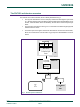
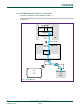
UM10936 PN7150 User Manual The PN7150 architecture overview The PN7150 is an NFC Controller, which is briefly described in Fig 1: • The top part describes the Device Host (DH) architecture with Higher Layer Driver (e.g. Android stack) hosting the different kind of applications (Reader/Writer, Peer to Peer, Card Emulation in the DH-NFCEE), the NCI driver & the transport layer driver. • The PN7150 is the NFCC in the Fig 1. It is connected to the DH through a physical interface which is an I2C.
UM10936 PN7150 User Manual For contactless operation, several Modes of operation are possible, based on the overall system described above. 1.1 Reader/Writer Operation in Poll Mode This mode of operation is further detailed in chapter →6. The Reader/Writer application running on the DH is accessing a remote contactless Tag/Card, through the PN7150.
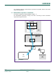
UM10936 PN7150 User Manual 1.2 Card Emulation Operation in Listen Mode This mode of operation is further detailed in chapter →7. An external Reader/Writer accesses the DH-NFCEE emulating a contactless card, through the PN7150. DH-NFCEE Reader Card P2P / Writer Emulat° NCI driver Transport layer driver DH I²C host interface Transport Layer FW NFCC NCI firmware RF Antenna TAG or Card Reader/Writer or P2P Fig 3.
UM10936 PN7150 User Manual 1.3 Peer to Peer Operation in Listen & Poll Mode This mode of operation is further detailed in chapter →8 The P2P application running on the DH is accessing a remote Peer device, through the PN7150. DH-NFCEE Reader Card P2P / Writer Emulat° NCI driver Transport layer driver DH I²C host interface Transport Layer FW NFCC NCI firmware RF Antenna TAG or Card Reader/Writer or P2P Fig 4.
UM10936 PN7150 User Manual 2. NCI Overview The aim of this section is to give an overview of the key points of the [NCI] specification. 2.1 NCI Components Here below are described the NCI component as defined in [NCI] which are located in the NFCC embedded FW. NFCEE Interfaces NFCEE Discovery RF Interfaces RF Discovery NCI modules (...) NCI Core Transport Mapping 1 Transport Mapping 2 Transport 1 Transport 2 (...) Transport Mapping n Transport n Fig 7. NCI components 2.1.
UM10936 PN7150 User Manual 2.1.3 Transport Mappings Transport Mappings define how the NCI messaging is mapped to an underlying NCI Transport, which is a physical connection (and optional associated protocol) between the DH and the NFCC. Each Transport Mapping is associated with a specific NCI Transport (see [NCI] for definition). 2.2 NCI Concepts This chapter outlines the basic concepts used in [NCI].
UM10936 PN7150 User Manual DH NFCC Command Response Notification Control Message Exchange Fig 9. Control Message Exchange 2.2.2 Data Messages Data Messages are used to transport data to either a Remote NFC Endpoint (named RF Communication in NCI) or to an NFCEE (named NFCEE Communication). NCI defines Data Packets enabling the segmentation of Data Messages into multiple Packets. Data Messages can only be exchanged in the context of a Logical Connection.
UM10936 PN7150 User Manual 2.2.3 Interfaces An NCI Module may contain one Interface. An Interface defines how a DH can communicate via NCI with a Remote NFC Endpoint or NFCEE. Each Interface is defined to support specific protocols and can only be used for those protocols (the majority of Interfaces support exactly one protocol). NCI defines two types of Interfaces: RF Interfaces and NFCEE Interfaces. Protocols used to communicate with a Remote NFC Endpoint are called RF Protocols.
UM10936 PN7150 User Manual 2.2.5 NFCEE Communication The DH can learn about the NFCEEs connected to the NFCC by using the NFCEE Discovery module. During NFCEE Discovery the NFCC assigns an identifier for each NFCEE. When the DH wants to communicate with an NFCEE, it needs to open a Logical Connection to the NFCEE using the corresponding identifier and specifying the NFCEE Protocol to be used.
UM10936 PN7150 User Manual 2.3 NCI Packet Format 2.3.1 Common Packet Header All Packets have a common header, consisting of an MT field and a PBF field: 3 (bits) MT 1 P B F Information Octet 0 Octet 1 - N Fig 11. NCI Core Packet Format Message Type (MT) The MT field indicates the contents of the Packet and SHALL be a 3 bit field containing one of the values listed in Table 1, below. The content of the Information field is dependent on the value of the MT field.
UM10936 PN7150 User Manual 2.3.2 Control Packets The Control Packet structure is detailed below. Packet Header 3 MT 4 1 P B F GID Octet 0 1 1 R F U R F U 6 8 L bytes OID Payload Length (L) Payload Octet 1 Octet 2 Octet 3... Octet (2+L) Fig 12. Control Packet Format Each Control Packet SHALL have a 3 octet Packet Header and MAY have additional payload for carrying a Control Message or a segment of Control Message.
UM10936 PN7150 User Manual 2.3.3 Data Packets The Data Packet structure is detailed below. Packet Header 3 MT 1 4 P B F Conn ID Octet 0 8 L bytes Payload Length (L) Payload 8 RFU Octet 1 Octet 2 Octet 3 ... Octet (2+L) Fig 13. Data Packet Structure Each Data Packet SHALL have a 3 octet Packet Header and MAY have additional Payload for carrying a Data Message or a segment of a Data Message. NOTE: In the case of an ‘empty’ Data Message, only the Packet Header is sent.
UM10936 PN7150 User Manual 2.3.4 Segmentation and Reassembly The Segmentation and Reassembly functionality SHALL be supported by both the DH and the NFCC. Segmentation and Reassembly of Messages SHALL be performed independently for Control Packets and Data Packets of each Logical Connection. Any NCI Transport Mapping is allowed to define a fixed Maximum Transmission Unit (MTU) size in octets.
UM10936 PN7150 User Manual 3. DH interface 3.1 Introduction The I²C interface of the PN7150 is compliant with the I²C Bus Specification V3.0, including device ID and Soft Reset. It is slave-only, i.e. the SCL signal is an input driven by the host. ! NCI packets can be as long as 258 Bytes. If the DH I²C peripheral has a buffer limitation which is below 258 Bytes, then a fragmentation mechanism SHALL be used at the I²C transport layer, as defined in →3.6.
UM10936 PN7150 User Manual SDA I²C Stop SCL I²C Start It may send an I²C NACK (negative acknowledge) when none of the buffers used by the NCI core in the PN7150 is free, which may happen in case PN7150 is in standby mode. If one single byte of a complete NCI frame is NACKed by the PN7150, the DH has to resend the complete NCI frame and not only this single byte.
UM10936 PN7150 User Manual As indicated on Fig 15, in case the PN7150 requests a data transfer by raising the IRQ pin and the DH tries to initiate a write sequence by positioning the write bit to 0b, the PN7150 keeps the IRQ active until the DH starts a read sequence. The DH is not allowed to proceed with a write sequence once the PN7150 has set the IRQ pin to its active value (logical ‘1’ in Fig 15).
UM10936 PN7150 User Manual ! The I²C fragmentation implemented on PN7150 requires that the DH waits until it has received a Control Message of type Response in response to a Control Message of type Command before it can send any Data Message. The DH also has to wait until it has received a Credit Notification to release the credit consumed by a previous Data Message it has sent, before it can send a new Control Message of type Command. 3.6.
UM10936 PN7150 User Manual The next figure shows this sequence: DH sends the 1st Fragment DH waits for WaitTime = 500µs DH sends I²C [Addr & R/W] Byte Did NFCC acknowledge ? no yes DH writes the next fragment Is the NCI packet fully transmitted ? no yes Fig 17. cI²C transport fragmentation algorithm, from DH point of view UM10936 User manual COMPANY PUBLIC All information provided in this document is subject to legal disclaimers. Rev. 2.
UM10936 PN7150 User Manual 3.6.2 Illustration of the I²C fragmentation: The 2 next figures illustrate a transfer of an NCI message implying I²C fragmentation, with a fragment size of 36 Bytes maximum, when: • The NCI message fits over a single NCI packet • The NCI message fits over multiple NCI packets (NCI segmentation is used on top of I²C fragmentation) Fig 18.
UM10936 PN7150 User Manual Fig 19. I²C Fragmentation when 1 NCI message is segmented into NCI packets UM10936 User manual COMPANY PUBLIC All information provided in this document is subject to legal disclaimers. Rev. 2.
UM10936 PN7150 User Manual 5. Initialization & Operation configuration 5.1 Reset / Initialization [NCI] defines a Reset/Initialization sequence, which is based on two different commands: CORE_RESET_CMD CORE_INIT_CMD These two commands have to be called by the DH in an “atomic” way: there cannot be any other command in-between and the PN7150 operation cannot start any operation (Reader/Writer, Card Emulation, P2P, Combined modes etc…) if it does not first receive these 2 commands.
UM10936 PN7150 User Manual ! PN7150B0HN/C11006 exposes FW version “01.AE”, while previous IC versions exposes FW version ’01.A0”. 5.3 Whole sequence to prepare the PN7150 operation After the Reset/Initialization sequence is passed, the PN7150 requires several other steps before it is ready to start operating as a Reader/Writer, Card Emulator etc… The simplest case is when the DH issues a CORE_RESET_CMD with Reset Type = Keep Configuration.
UM10936 PN7150 User Manual On this figure, Green background means mandatory exchange Blue background means optional exchange, depending on the use case.
UM10936 PN7150 User Manual 5.4 Proprietary command to enable proprietary extensions It is visible on the previous flow chart that NXP has introduced a proprietary command sent by the DH to enable the proprietary extensions to [NCI], which are available in the PN7150. So, when the PN7150 receives this command NCI_PROPRIETARY_ACT_CMD, it knows that the DH is aware of the proprietary extensions and may therefore send proprietary notifications (see the list in Table 12).
UM10936 PN7150 User Manual 5.6 PLL input Clock Management The PN7150 is flexible in terms of clock sources. It can be either: a 27.12MHz quartz or a clean clock signal available on the platform on which PN7150 is connected. A PLL inside PN7150 will convert this input clock signal into an internal 27.12MHz used to generate the RF carrier. The input clock frequency has to be one of the predefined set of input frequencies: 13MHz, 19.2MHz, 24MHz, 26MHz, 38.4MHz and 52MHz.
UM10936 PN7150 User Manual 5.7.1 CFG1: Transmitter supply voltage from battery supply In CFG 1 VBAT1 and VBAT2 are connected to the Battery and between 2.3V and 5.5V. Fig 28. CFG1: VBAT1 = VBAT2 = 2.3V to 5.5V This configuration is enabled by appropriate setting of PMU_CFG parameter. In addition TVDDReqTime parameter shall be set to 0x00 (see configuration chapter →10.1). 5.7.
UM10936 PN7150 User Manual 6. Reader/Writer Mode 6.1 T1T, T2T, MIFARE Ultralight, MIFARE Classic and MIFARE Plus tags Note: all the Tags/Cards in this category are based on NFC-A technology, but they do not support the ISO-DEP Protocol. MIFARE Plus cards support the ISO-DEP protocol, but only when they are configured in Security Level3, which is out of scope for this section. 6.1.1 Access through the [NCI] Frame RF Interface [NCI] allows the data exchange with tags T1T, T2T using the Frame RF Interface.
UM10936 PN7150 User Manual 6.1.2 [PN7150-NCI] extension: TAG-CMD Interface In addition to the incompatibility of the Frame RF Interface with the MIFARE Classic Authenticate command described in the previous chapter, the intention when introducing the TAG-CMD interface was to add some commands such as ReadN/WriteN which would allow to read/write multiple bytes, and would rely on the NFCC to call several times the basic read/write commands defined in the T1T, T2T or MIFARE Classic protocols.
UM10936 PN7150 User Manual Byte 0 NCI data packet structure Msg Conn ID Type Byte 0 REQs Frame structure Msg Conn ID Type Byte 0 RSPs Frame structure Msg Conn ID Type Byte 1 Byte 2 RFU Payload Length Byte 1 Byte 2 Byte 3 Byte 4 Byte 5 RFU Payload Length REQ ID Parameter 1 (optional) Parameter 2 (optional) Byte 1 Byte 2 Byte 3 RFU Payload Length RSP ID PAYLOAD DATA (if any) Byte n DATA (if any) RF Status Fig 31.
UM10936 PN7150 User Manual 6.1.5 [PN7150-NCI] extension: List of REQs & RSPs In this section, the following acronyms are used: Table 30. Acronyms definition Acronym Description T1T NFC FORUM Type 1 Tag (based on Topaz/Jewel) MF MIFARE family, not ISO-DEP compliant, including T2T, MIFARE Ultralight (std or C), MIFARE Classic and MIFARE Plus for Security Level 1 & 2. MFC MIFARE Classic and MIFARE Plus for Security Level 1 & 2.
UM10936 PN7150 User Manual Table 33. RSP_ID RSP Name 0x10 XCHG_DATA_RSP XCHG_DATA_RSP Presence Description of Data Yes MFC: DH gets Raw data once RF data from MFC are decrypted by the NFCC, if successful. T1T/T2T: DH gets Raw plain data once the NFCC receives RF data from the Tag, if successful. If the response from the MF tag in the field is an ACK or a NACK, the ACK/NACK is also sent back to the DH inside the Data field.
UM10936 PN7150 User Manual Table 38. MFC_Authenticate_REQ parameters Length Parameter Value (Byte) 1 Sector Address 1 2 Key Selector 1 Description Address of the sector to authenticate N/A Bit Mask b7 b6 b5 b4 b3 Description b2 b1 b0 Key A (‘0’) or Key B (‘1’) X X X 0 3 Table 39.
UM10936 PN7150 User Manual DH NCI RF NFCC Endpoint RF_DISCOVER_MAP_CMD Map MIFARE Classic prot. to TAG-CMD Intf RF_DISCOVER_MAP_RSP Start Discovery (move to RFST_DISCOVERY) (RF Prot. = MF_CLASSIC,Mode = Poll, RF Intf. = TAG-CMD, ...) RF_DISCOVER_CMD(NFC_A_PASSIVE_POLL_MODE, ...) RF_DISCOVER_RSP RF Field On Activation sequence: driven by the NFCC REQA/ATQA AntiColl CL1 SELECT/SAK NFCC activates the TAG-CMD intf: move to RFST_POLL_ACTIVE SAK shows MIFARE Classic with bit b4=1b (see AN10833).
UM10936 PN7150 User Manual 6.1.9 Access through the TAG-CMD RF Interface The TAG-CMD RF interface allows full access to all the Tags based on NFC-A technology and not supporting the ISO-DEP protocol, leaving up to the PN7150 to manage the low level TAG-CMD: Table 41.
UM10936 PN7150 User Manual Command Main Parameters RF_DISCOVER_CMD RF Technology & Mode Values PF_RC_CODE NFC_F_PASSIVE_POLL_MODE 6.3 T4T & ISO-DEP Tags/Cards [NCI] allows the data exchange with a T4T tag or an ISO-DEP tag by using the Frame RF Interface or the ISO-DEP RF Interface, so there is no need to define a proprietary RF interface here. 6.3.
UM10936 PN7150 User Manual Main Parameters Command Values Mode Poll RF Interface Frame PB_AFI CORE_SET_CONFIG_CMD PB_BAIL_OUT 1 PB_SENSB_REQ_PARAM 2 RF_DISCOVER_CMD RF Technology & Mode NFC_B_PASSIVE_POLL_MODE * Note: RF_DISCOVER_MAP_CMD is optional since the mapping to Frame RF Intf. is done by default 1 this parameter is not active in PN7150: it can be read/written, but PN7150 will always behave with Bail Out in NFC-A, whatever the value written by the DH to that parameter.
UM10936 PN7150 User Manual 2 this parameter is not supported in PN7150: STATUS_INVALID_PARAM will be returned to the DH if it attempts to write this parameter. Here are the commands and configuration parameters to prepare the Reader/Writer Mode for ISO-DEP through the ISO-DEP Interface for technology NFC-B: Table 49. Config. seq.
UM10936 PN7150 User Manual Table 51. GID 1111b RF_PRES-CHECK_RSP Numbers of OID Description parameter(s) 0x11 1 The NFCC acknowledges the command received from the DH. Table 52. RF_PRES-CHECK_RSP parameters Payload Field(s) Length Value/Description STATUS Table 53.
UM10936 PN7150 User Manual Table 56. RF_T4T_SBLOCK_PARAM_CMD parameters Payload Field(s) Length Value/Description N* Octets S-Block S(PARAMETERS) to send; the payload only has to be provided (i.e. PARAMETERS), NFCC will encapsulate it in an S-Block. ABI * PN7150 supports maximum 10 Bytes for ABI length Table 57. GID 1111b RF_T4T_SBLOCK_PARAM_RSP Numbers of OID Description parameter(s) 0x10 1 The NFCC acknowledges the command received from the DH. Table 58.
UM10936 PN7150 User Manual 6.3.5 [PN7150-NCI] extension: WTX notification After data was sent to the card/tag, it can request an additional processing time before sending data response. This is done with WTX (Waiting Time Extension) request. If WTX REQ/RESP exchange phase continues a NCI system notification WTX is sent with a period configurable via READER_FWITOX_NTF_CFG. Table 61. GID 1111b PH_NCI_OID_SYSTEM_WTX Numbers of OID Description parameter(s) 0x17 6.3.
UM10936 PN7150 User Manual Detailed ISO-DEP RF Interface activation handling in the NFCC: For NFC-A: Following the anticollision sequence, if the Remote NFC Endpoint supports ISO-DEP Protocol, the NFCC sends the RATS Command to the Remote NFC Endpoint. And after receiving the RATS response, the PN7150 MAY send the PPS command if PI_BIT_RATE was set by the DH to an allowed value higher than 0x00.
UM10936 PN7150 User Manual Table 63. Config. seq. for R/W of NFC-15693 through the Frame RF Interface Command Main Parameters Values RF Protocol PROTOCOL_15693 RF_DISCOVER_MAP_CMD * Mode RF_DISCOVER_CMD Poll RF Interface Frame RF RF Technology & Mode NFC_15693_PASSIVE_POLL_MODE * Note: RF_DISCOVER_MAP_CMD is optional since the mapping to Frame RF Intf. is done by default 6.4.
UM10936 PN7150 User Manual ! PN7150 is parsing the bit Option Flag (bit b7 in the request Flags Byte, as defined in ISO15693) to check if this bit is set by the DH or not. If set, this indicates that the tag is from TI, and PN7150 is sending commands over RF using a special mode, as defined for some commands in ISO15693. Data from RF to the DH The NCI Data Message corresponds to the Payload of the Response Format defined in [ISO15693-3] Section 7.4, followed by a Status field of 1 octet.
UM10936 PN7150 User Manual • PN7150 is in state RFST_W4_ALL_DISCOVERIES, it sends an RF_DISCOVER_NTF to the DH for VICC2 and moves to RFST_W4_HOST_SELECT. • PN7150 is in state RFST_W4_ALL_DISCOVERIES and waits for the DH to select one of the 2 VICCs. Once it receives the RF_DISCOVER_SELECT_CMD from the DH, PN7150 immediately activates the Frame RF Interface and does not check if the selected VICC is still in the field.
UM10936 PN7150 User Manual Table 66. Config. seq. for R/W of Kovio tags through the Frame RF Intf Command Main Parameters Values RF_DISCOVER_MAP_CMD* RF Protocol PROTOCOL_KOVIO Mode Poll RF Interface Frame RF Interface 1 CORE_SET_CONFIG_CMD PA_BAIL_OUT RF_DISCOVER_CMD RF Technology & Mode NFC_A_KOVIO_POLL_MODE * Note: RF_DISCOVER_MAP_CMD is optional since the mapping to Frame RF Intf.
UM10936 PN7150 User Manual 7. Card Emulation Mode The PN7150 supports Card Emulation hosted by the DH based on either technology NFCA, NFC-B or NFC-F. 7.1 ISO-DEP card emulation through NFC-A & NFC-B [NCI] defines all the mechanisms necessary to implement this feature. Two options are possible: 1. The DH wants to manage by itself the ISO-DEP protocol; it SHALL then map the ISO-DEP protocol on the Frame RF Interface. ! Not supported in PN7150 2.
UM10936 PN7150 User Manual Main Parameters Command Values LB_APPLICATION_DATA LB_SFGI LB_ADC_FO LI_FWI LB_H_INFO_RESP 1 LI_BIT_RATE RF_DISCOVER_CMD RF Technology & Mode NFC_B_PASSIVE_LISTEN_MODE 1 this parameter is not active in PN7150: it can be read/written, but PN7150 will always behave with empty Higher Layer – Response field in the ATTRIB response, whatever the value written by the DH to that parameter. 7.2 T3T card emulation through NFC-F 7.2.
UM10936 PN7150 User Manual * Note : RF_DISCOVER_MAP_CMD is optional since the mapping to Frame RF Intf. is done by default UM10936 User manual COMPANY PUBLIC All information provided in this document is subject to legal disclaimers. Rev. 2.
UM10936 PN7150 User Manual 8. P2P Initiator & Target Mode 8.1 P2P Passive mode [NCI] defines all the mechanisms necessary to implement this feature. Two options are possible: 1. The DH wants to manage by itself the NFC-DEP protocol; it SHALL then map the NFC-DEP protocol on the Frame RF Interface. ! Not supported in PN7150 2. The DH leaves the NFC-DEP protocol management to the NFCC: it SHALL then map the NFC-DEP protocol on the NFC-DEP interface.
UM10936 PN7150 User Manual Table 72. Config. seq. of NFC-DEP/NFC-A&F Passive Initiator over NFC-DEP RF Intf Command Main Parameters Values RF_DISCOVER_MAP_CMD RF Protocol PROTOCOL_NFC-DEP Mode Poll RF Interface NFC-DEP PA_BAIL_OUT PF_BIT_RATE CORE_SET_CONFIG_CMD PF_RC_CODE PN_NFC_DEP_SPEED PN_ATR_REQ_GEN_BYTES PN_ATR_REQ_CONFIG RF_DISCOVER_CMD RF Technology & Mode NFC_A_PASSIVE_POLL_MODE RF Technology & Mode NFC_F_PASSIVE_POLL_MODE 8.
UM10936 PN7150 User Manual Command RF_DISCOVER_CMD Main Parameters Values RF Technology & Mode NFC_A_ACTIVE_LISTEN_MODE RF Technology & Mode NFC_F_ACTIVE_LISTEN_MODE Here are the commands and configuration parameters to prepare the NFC-DEP Initiator for technologies NFC-A and NFC-F in the DH through the Frame RF Interface: Table 74. Config. seq.
UM10936 PN7150 User Manual 9. RF Discovery Management 9.1 RF Discovery functionalities This contains the overall RF Discovery concepts applied in PN7150. [NCI] defines the general RF state machine allowing the NFC controller to discover either cards or readers or peers. This RF state machine contains a state called RFST_DISCOVERY where the RF Discovery profile is applied.
UM10936 PN7150 User Manual RF_DISCOVER_SELECT_CMD/RSP CORE_INTF_ERROR_NTF (RF_xxx_ERROR) RF_DEACTIVATE_CMD/RSP RF_PRES_CHECK_ (Idle Mode) CMD/RSP/NTF RF_INTF_ACTIVATED_NTF (Poll Mode) RFST_ POLL_ ACTIVE RFST_W4_ HOST_ SELECT RF_DEACTIVATE_CMD/RSP/NTF (Sleep Mode) RF_DEACTIVATE_CMD/RSP/NTF (Sleep_AF Mode) RF_DEACTIVATE_CMD/RSP/NTF (Idle Mode) RF_INTF_ACTIVATED_NTF (Poll Mode) RF_DEACTIVATE_CMD/RSP/NTF (Discovery) or RF_DEACTIVATE_NTF (Discovery, Link Loss) CORE_GENERIC_ERROR_NTF (DISC_TG_ACT_FAILED
UM10936 PN7150 User Manual RF_DEACTIVATE_CMD(Discovery) RFST_LISTEN_SLEEP. in RFST_LISTEN_ACTIVE or 9.2 NFC FORUM Profile as defined in [NCI] The NFC FORUM profile is the implementation of the RF discovery activity as defined in the NFC FORUM (see [ACTIVITY] specification). [NCI] only covers technologies NFC-A, NFC-B & NFC-F. So the basic NFC FORUM profile will poll for these technologies only. Furthermore, for NFC-F, only one bit rate is used during the polling phase.
UM10936 PN7150 User Manual 9.3 [PN7150-NCI] extension: additional technologies not yet supported by the NFC FORUM PN7150 supports more technologies than currently supported by the NFC FORUM specifications: P2P Active, ISO15693 VCD and KOVIO Reader. Furthermore, PN7150 offers an additional proprietary value for the configuration parameter PF_BIT_RATE, which allows configuring for both 212 kbps & 424 kbps to be polled in NFCF in Passive Mode.
UM10936 PN7150 User Manual Listening phase NFC-A Active NFC-A NFC-B NFC-F @424 NFC-F @212 15693 Polling phase Fig 37. RF Discovery sequence in case of NFC FORUM+ profile Note: the transition from the Poll NFC-A Active phase to the Poll NFC-A (passive) is done through an RF field off/on sequence. For more details concerning the different phases duration, guard time, Bailout, please refer to the configuration section (chapter →10.2) where all these parameters are defined. 9.
UM10936 PN7150 User Manual 2 antennas. The LPCD is therefore monitoring the antenna impedance, to see if there is a significant variation which is interpreted as being caused by a Card/Tag being in proximity. To achieve that, the LPCD periodically generates very short pulses of RF Field, without any modulation, and measures some antenna characteristics during this pulse. The time between these RF pulses is defined by the TOTAL_DURATION parameter, as specified for the RF Discovery in [NCI].
UM10936 PN7150 User Manual The figure below compares the RF Discovery with the LPCD disabled to the RF Discovery with the LPCD enabled and highlights the impact on the average current consumption (the assumption being here that TOTAL_DURATION ~ 300ms): RF Discovery with LPCD disabled, NFC-A & NFC-B only in Poll Mode One complete RF Discovery Loop: Period = TOTAL_DURATION Listen Phase Poll Phase Poll A Listen Phase Poll B Poll Phase Poll A Listen Phase Poll B RF Field t Imax Current consumption A
UM10936 PN7150 User Manual 9.4.2 Configuration of the Technology Detection Activity when the LPCD has detected an "object" As described in the previous chapter, once the PN7150 detects a change in the antenna impedance, it performs a Technology Detection as defined in [ACTIVITY] which tries to activate the “object” by sending Request Commands from the different technologies configured for the RF Discovery.
UM10936 PN7150 User Manual 9.4.3 Notification when the Trace Mode is enabled The Low Power Card Detector needs to be tuned in each application; it is therefore useful to get some information from PN7150 so that the Low Power Card Detector can be appropriately configured. The Low Power Card Detector can be configured to enable a Trace Mode, where the following Notification will be sent to the DH by PN7150: Table 76.
UM10936 PN7150 User Manual NFC-A Polling phase NFC-B Wait phase (no Listen) Fig 41. RF Discovery sequence in case of EMVCo profile If there is a card detected in the field, then the polling sequence is modified by the PN7150, in order to look for another potential card in the field. This is illustrated by the 2 figures below: On the 1st one, there is no card in the RF Field, so PN7150 keeps polling by alternating WUPA & WUPB commands.
UM10936 PN7150 User Manual 1xNFC-A Card in the Field, No NFC-B Card 1 NFC-A Card => Response No NFC-B Card => no response Payment transaction proceeds 1 NFC-A Card => Response NFCC = PCD WUPA WUPB HLTA WUPA Anticoll + Select Fig 43. EMVCo polling with NFC-A card in the field ! 9.5.1.2 In PN7150 the Low Power Card Detector is automatically disabled when the EMVCo profile is enabled, since these 2 features are conflicting if simultaneously enabled.
UM10936 PN7150 User Manual RF_DEACTIVATE_NTF(Discovery, Link Loss). In such a way, when PN7150 has detected a timeout or an unrecoverable protocol error during the RF communication with the PICC, it will autonomously come back to RFST_DISCOVERY, switching off the RF Field, as requested by EMVCo and then restarting the Polling phase in a timely manner, as requested by EVMCo. This new transition is graphically described in Fig 35. 9.5.
UM10936 PN7150 User Manual 9.6.1 CORE_SET_POWER_MODE Command/Response ! Table 78. GID 1111b The Standby Mode is enabled by default. Given the very strong impact on the power consumption, disabling the Standby Mode should be restricted to debug sessions. CORE_SET_POWER_MODE_CMD Numbers of OID Description parameter(s) 0x00 1 Command to request the PN7150 to enable/disable the Standby Mode Table 79. CORE_SET_POWER_MODE_CMD parameter Payload Field(s) Length Value/Description Mode Table 80.
UM10936 PN7150 User Manual 10. Configurations When the DH needs to update the value of the parameters described hereafter, it shall send a CORE_RESET_CMD/CORE_INIT_CMD sequence after the CORE_SET_CONFIG_CMD, to ensure that the new value is used for the parameters. ! If numerous parameters are updated thanks to multiple CORE_SET_CONFIG_CMD commands, a single CORE_RESET_CMD/ CORE_INIT_CMD sequence is enough after the last CORE_SET_CONFIG_CMD.
UM10936 PN7150 User Manual Name & Rights Description Input Clock selection & configuration for the internal 13.56MHz RW in E²PROM CLOCK Bits [4:3] Clk Source Description CLOCK_SEL_CFG 01b XTAL 10b PLL 11b RFU 00b RFU Ext. Tag Len. Default Value 0xA0 0x03 1 0x08 0xA0 0x04 1 0x01 A 27.
UM10936 PN7150 User Manual Name & Rights Description IRQ_POLARITY_CFG Configuration of the IRQ pin polarity RW in E²PROM Bit Mask b7 b6 b5 b4 b3 b2 b1 0 Default Value 0xA0 0x05 1 0x00 0xA0 0x06 1 0x00 0xA0 0x07 1 0x03 b0 I²C transport fragmentation '1' => enabled, '0'=> disabled IRQ PIN polarity config. X 0 Len. Description X 0 Ext. Tag 0 0 0 All these bits SHALL be set to logical ‘0’ (RFU) b1=’0’ => PN7150 requests to transmit when IRQ pin = ’1’.
UM10936 PN7150 User Manual Name & Rights Description TO_BEFORE_STDBY_ CFG Timeout used to wait after last DH-NFCEE communication before going into standby (from 0 to 65.536s in steps of 1ms). Default Value Ext. Tag Len. 0xA0 0x09 2 0x03E8 (1s) 0xA0 0x0A 1 0x00 RW in E²PROM Applies only when the discovery is stopped and standby mode is activated by SET_PWR_MODE_CMD. Pay attention that the parameter value is defined in little endian (LSB first).
UM10936 PN7150 User Manual Name & Rights Description PMU_CFG Configuration of the Power Management Unit (PMU) Ext. Tag Len. 0xA0 0x0E 3 0xA0 0x14 32 0xA0 0x92 68 RW in E²PROM Byte 0: Bit Mask b7 b6 b5 b4 0 0 0 0x020900 (CFG1) Description b3 b2 b1 b0 X 0 Default Value 0 VBAT1 connected to 5V 0 - CFG1, 1 - CFG2 1 0 RFU Byte 1: Bit Mask b7 b6 b5 b4 Description b3 b2 b1 b0 TVDD monitoring threshold: 0 - 3.
UM10936 PN7150 User Manual Table 83. DYN_LMA_SETTINGS_CFG Description Len. Default Value RFU 2 N/A bLutSize: Size of LUT, DO NOT MODIFY this parameter 1 0x10 1 0x00 4 dwLutEntry0: bits 20:18 = TXLDO output voltage: PMU_TXLDO_CONTROL_REG/TXLDO_SELECT bits 17:16 = CLIF_ANA_TX_AMPLITUDE_REG / TX_CW_AMPLITUDE_ALM_CM bit 15 = CLIF_TX_CONTROL_REG / TX_ALM_TYPE_SELECT bits 14:10 = CLIF_ANA_TX_AMPLITUDE_REG / TX_RESIDUAL_CARRIER bits 09:00 = AGC_VALUE 4 0x037C02 ... dwLutEntry… 4 N/A 64 ...
UM10936 PN7150 User Manual Ext. Tag Len. Default Value 0xA0 0x43 1 0x50 0xA0 0x44 1 0x00 GT_NFC-AA_CFG 0xA0 0x46 2 0x21C4 (5.1ms) GT_NFC-AP_CFG Guard time (in steps of 0.59µs) used between the start of st RW in E²PROM unmodulated RF field & 1 command for Poll NFC-A Passive (min=’0001’, max=’FFFF’) 0xA0 0x47 2 0x2219 (5.15ms) GT_NFC-B_CFG Guard time (in steps of 0.
UM10936 PN7150 User Manual Name & Rights Description MFC_KEY-3_CFG Default Value Ext. Tag Len. Key 3, used in MIFARE Classic Authentication command. 0xA0 0x50 6 0xFFFF FFFF FFFF Key 4, used in MIFARE Classic Authentication command. 0xA0 0x51 6 0xFFFF FFFF FFFF Key 5, used in MIFARE Classic Authentication command. 0xA0 0x52 6 0xFFFF FFFF FFFF Key 6, used in MIFARE Classic Authentication command. 0xA0 0x53 6 0xFFFF FFFF FFFF Key 7, used in MIFARE Classic Authentication command.
UM10936 PN7150 User Manual Name & Rights Description Ext. Tag Len. Default Value 0xA0 0x5F 1 0x00 0xA0 0x61 1 0x00 In both cases, the RF_INTF_ACTIVATED_NTF will NOT embed the RID response from the T1T, as defined in [NCI]. TSN value transported by the PN7150 in the SENSF_REQ RW in E²PROM command: the DH defines the number of time slots for collision resolution.
UM10936 PN7150 User Manual 10.2.2 Listen Mode Table 85. Listen Mode Configuration Name & Rights Description Ext. Tag Specifies the time out (in ms) applied by PN7150 before it 0xA0 0x80 RW in E²PROM restarts a Polling sequence, after it has detected a Field OFF in Listen Mode TO_RF_OFF_CFG LISTEN_PROFILE_SEL_ CFG RW in E²PROM LISTEN_ISODEP_FSCI_ CFG RW in E²PROM Len.
UM10936 PN7150 User Manual Name & Rights Description Ext. Tag Len. Default Value The list of transition IDs and the appropriate values for the Register offset & its value is available in [AN 11755], as referenced in →15 CORE_SET_CONFIG_CMD command to set RF Transitions triggers internal EEPROM memory page write operation. To prevent memory corruption, any interruption of this command (between CORE_SET_CONFIG_CMD and CORE_SET_CONFIG_RSP) by hardware reset or power off MUST be prevented.
UM10936 PN7150 User Manual Table 89. GID 1111b Payload Field(s) Length Value/Description CLIF Register Offset 1 Octet Offset of the register to read out from the CLIF RF_ GET_TRANSITION_RSP Numbers of OID Description parameter(s) 0x14 2 The PN7150 acknowledges the command received from the DH and sends the RF Transition value to the DH. Table 90.
UM10936 PN7150 User Manual 11. Test Mode 11.1 Test Session The PN7150 has the ability to generate a continuous PRBS pattern on the RF interface. Whatever the test command used by the DH, it is necessary to implement a "test session", which isolates the test mode from a regular "NCI session" of PN7150.
UM10936 PN7150 User Manual Table 93. GID 1111b TEST_PRBS_RSP Numbers of OID parameter(s) 0x30 1 Description PN7150 reports if the TEST_PRBS_CMD is successful or not. Table 94. TEST_PRBS_RSP parameters Payload Field(s) Length Value/Description STATUS ! 1 Octet 0x00 STATUS_OK 0x06 STATUS_SYNTAX_ERROR 0x09 STATUS_INVALID_PARAM Others Forbidden The only way to stop the on-going PRBS pattern generation is to apply a HW reset (through the VEN pin). 11.
UM10936 PN7150 User Manual Table 97. Meas. ID 0x01 0x02 0x04 0x201 Parameters to include in TEST_ANTENNA_CMD depending on the measurement to perform Param.
UM10936 PN7150 User Manual Payload Field(s) Length Value/Description Result_Parameter_2 1 Octet Value depending on the measurement performed : see →Table 101 Result_Parameter_3 1 Octet Value depending on the measurement performed : see →Table 101 Result_Parameter_4 1 Octet Value depending on the measurement performed : see →Table 101 Table 100. Parameters provided in TEST_ANTENNA_RSP as a result of the measurement performed Meas. Measurement Param.
UM10936 PN7150 User Manual Table 101. TEST_GET_REGISTER_CMD Numbers of GID OID Description parameter(s) 1111b 0x33 0 Command to retrieve AGC_VALUE_REGISTER the Value of the Table 102. TEST_GET_REGISTER_CMD parameters Payload Field(s) Length Value/Description Fix parameters 4 Octet The parameters have fixed values and shall be 0x40 0x00 0x40 0xD8. Table 103.
UM10936 PN7150 User Manual 12. PN7150 Practical approach 12.1 Basic examples for Reader/Writer Mode 12.1.1 R/W Mode with 1 NFC endpoint DH NCI RF NFCC Endpoint Map ISO-DEP protocol to Frame RF Interface (optional, done by default) RF_DISCOVER_MAP_CMD (RF Prot. = ISO_DEP,Mode = Poll, RF Intf.
UM10936 PN7150 User Manual DH NCI RF NFCC Endpoint Map ISO-DEP protocol to ISO-DEP RF Interface RF_DISCOVER_MAP_CMD (RF Prot. = ISO_DEP,Mode = Poll, RF Intf.
UM10936 PN7150 User Manual 12.1.2 R/W Mode with 2 NFC endpoints DH RFST_IDLE NCI RF NFCC Endpoint 2 Map ISO-DEP protocol to ISO-DEP RF Interface RF_DISCOVER_MAP_CMD (RF Prot. = ISO_DEP,Mode = Poll, RF Intf. = ISO-DEP) RF_DISCOVER_MAP_RSP Start Discovery (move to RFST_DISCOVERY) Activation sequence RF_DISCOVER_CMD(NFC_A_PASSIVE_POLL_MODE) RF Field On RF_DISCOVER_RSP RFST_DISCOVERY REQA / ATQA AntiColl CL1 : Collision Detection RF_DISCOVER_NTF (RF Disc. ID = 0x01, RFST_W4_ALL_DISC.
UM10936 PN7150 User Manual DH NCI RF_DISCOVER_MAP_CMD RFST_IDLE RF NFCC Map ISO-DEP prot. to ISO-DEP RF Intf & NFC-DEP prot. To NFC-DEP Intf (RF Prot. = ISO_DEP,Mode = Poll, RF Intf. = ISO-DEP RF Prot. = NFC_DEP,Mode = Poll, RF Intf.
UM10936 PN7150 User Manual 12.2 Basic examples for Card Emulation Mode NCI DH NFCC RF Endpoint Map ISO-DEP protocol to ISO-DEP Interface RF_DISCOVER_MAP_CMD (RF Prot.=ISO-DEP, Mode=Listen, RF Intf.=ISO-DEP) RF_DISCOVER_MAP_RSP Fill the Listen Routing Table for protocol-based routing RF_SET_LISTEN_MODE_ROUTING_CMD (NFCEE ID=DH-NFCEE, Prot.
UM10936 PN7150 User Manual DH NCI RF NFCC Endpoint Map ISO-DEP protocol to ISO-DEP Interface RF_DISCOVER_MAP_CMD (RF Prot.=ISO-DEP, Mode=Listen, RF Intf.=ISO-DEP) RF_DISCOVER_MAP_RSP Fill the Listen Routing Table for protocol-based routing RF_SET_LISTEN_MODE_ROUTING_CMD (NFCEE ID=DH-NFCEE, Prot.
UM10936 PN7150 User Manual 12.3 Basic examples for P2P Passive Mode 12.3.1 Target in P2P Passive Mode / NFC-A @ 106kbps DH NCI RF NFCC Endpoint Map NFC-DEP protocol to NFC-DEP Interface RF_DISCOVER_MAP_CMD (RF Prot.=NFC-DEP, Mode=Listen, RF Intf.=NFC-DEP) RF_DISCOVER_MAP_RSP Fill the Listen Routing Table for protocol-based routing RF_SET_LISTEN_MODE_ROUTING_CMD (NFCEE ID=DH-NFCEE, Prot.
UM10936 PN7150 User Manual DH NCI RF NFCC Endpoint Map NFC-DEP protocol to NFC-DEP Interface RF_DISCOVER_MAP_CMD (RF Prot.=NFC-DEP, Mode=Listen, RF Intf.=NFC-DEP) RF_DISCOVER_MAP_RSP Fill the Listen Routing Table for protocol-based routing RF_SET_LISTEN_MODE_ROUTING_CMD (NFCEE ID=DH-NFCEE, Prot.
UM10936 PN7150 User Manual 12.3.2 Initiator in P2P Passive Mode DH NCI RF NFCC Endpoint Map NFC-DEP protocol to NFC-DEP RF Interface RF_DISCOVER_MAP_CMD (RF Prot. = NFC-DEP,Mode = Poll, RF Intf.
FCC Statement: Please take attention that changes or modification not expressly approved by the party responsible for compliance could void the user’s authority to operate the equipment. This device complies with Part 15 of the FCC Rules. Operation is subject to the following two conditions: (1) This device may not cause harmful interference, and (2) This device must accept any interference received, including interference that may cause undesired operation.
(1) Operational use conditions Module has professional users use condition limitations, Host product manufacturer please ensure giving such warning like “Product is limited to professional users use” in your product’s instruction. (2) Antenna used Antenna Max.
operating with the module is in compliant with Part 15B requirements. Please note that For a Class B or Class A digital device or peripheral, the instructions furnished the user manual of the end-user product shall include statement set out in §15.105 Information to the user or such similar statement and place it in a prominent location in the text of host product manual.