
Data Sheet
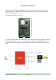


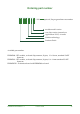

1. 32K jumper:
Since P16,P17 are multiplex with external 32.768KHz oscillator, this jumper allows the
PRBMD00 to connected with the on board 32.768JKHz oscillator.
2. LED & UART jumper:
This jumper allows the module to connected with on-board LED and the on-board
USB-UART chip. Connecting 5V allow PRBMD00 to be powered from USB.
Connecting 3V3 will provides a 3.3VDC to the rest of the board
3. TM Jumper
PRBMD00 goes into firmware programming mode if TM pin is connected to the 3V3 pin.
4. Reset button
Pressing this button to reset PRBMD00 module
5. USB-UART LED:
LEDs indicate UART traffic, yellow LED represents TXD and green LED represents RXD
6. module LED:
LEDs connect to the LED & UART jumper, user can makes use of these LED by shorting the
jumper.
7. VBus pin:
The EVK can be powered by USB port, or a 5VDC can be applied to this pin to power up the
board.
PRBMD00 DATASHEET 1.5
K-SOLUTION
22
PRBMD00
32K jumper
LED & UART jumper
TM jumper
Reset button
USB-UART LED
module LED